


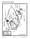
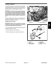

Spray System Operation
The Workman 200 Spray System uses a positive dis-
placement diaphragm pump to move spray solution
from the spray tank to the boom nozzles. The spray
pump is self–priming and has a dry crankcase. The
pump is driven by the transaxle PTO kit output shaft at
a speed that is proportional to the ground speed of the
vehicle. It should be noted that pump rotation will stop
whenever the vehicle clutch pedal is depressed.
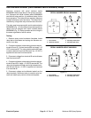
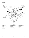
The downward stroke of the pumps’ connecting rods
and diaphragms create suction to allow fluid to be drawn
from the spray tank to the pump through the suction
tube, suction strainer, hoses, and connectors. A suction
dampener placed in the suction line dampens suction
pulses to smooth suction flow. Suction valves positioned
in the pump valve chamber prevent fluid from being
pumped back into the suction line when the connecting
rods change direction. Leaks in the suction line will
cause system problems and often will be indicated by er
-
ratic suction line jumping and pump noise.
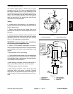
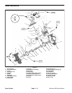
Once to the pump, the fluid is pushed by the upward
stroke of the pumps’ connecting rods and diaphragms
to the pressure side of the spray system through hoses,
connectors, control valves, and spray nozzles. A pres
-
sure dampener at the pump outlet smooths system
pressure pulsation. Pressure valves positioned in the
pump head prevent fluid from being drawn back into the
pump. Maximum pressure in the system is limited by a
pressure relief valve located in the tank. A pressure
gauge indicates system pressure.
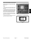
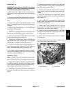
The spray system is controlled electrically and consists
of a rate control valve and three boom control valves. A
manually adjustable boom bypass valve exists in each
of the boom control valves to prevent system pressure
changes when a boom section is shut off. Flow in excess
of control valve settings is directed back to the spray
tank.
An inline flowmeter in the pressure side of the system di-
rectly before the boom control valves measures flow to
the spray booms. The Spray Pro Monitor displays infor
-
mation regarding application rate based on input from
the flowmeter and the ground speed sensor in the trans
-
axle.
Flow for tank agitation comes from flow that is bypassed
by the rate control valve. A manual agitation control
valve directs flow to four agitation nozzles in the spray
tank.
Spray
System
Workman 200 Spray System
Page 3 – 5
Spray System