


Workman 200 Ultra Sonic Boom System (Rev. C)Page 3.2 -- 27
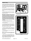
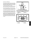
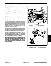
Sonic Boom Switch
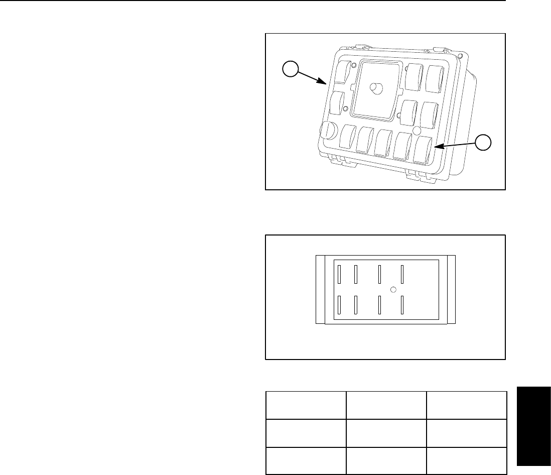
The sonic boom switch is used as an input for the Toro
electronic controller (TEC) to activate the Ultra Sonic
Boom System. This switch has two (2) positions: auto-
matic and manual. The sonic boom switch is located on
the spray control panel (Fig. 15).
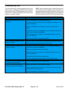
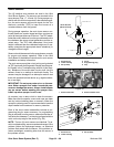
If the sonic boom switch is in the automatic position, the
sonic sensors willbe activatedto allow automaticmove-
ment of the booms. The tips of the booms will remain at
a constant distance from the ground. The boom lift
switchescanbeusedtoraise/lowertheboomswhenthe
sonic boom switch is in the automatic position. The light
in the switch should be illuminated when the switch is in
the automatic position.
If the sonic boom switch is in the manual position, the
sonic sensors are disabled. The boom lift switches are
used to raise/lower the booms when the sonic boom
switch is in the manual p osition.
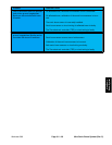
Testing
NOTE: Before disconnecting sonic boom switch for
testing, the switch and its circuit wiring should be tested
as a TEC input with the Diagnostic Display (see Diag-
nostic Display in the Troubleshooting section of this
chapter). If the Diagnostic Display verifies that the sonic
boom switch and circuit wiring are functioning correctly,
no further switch testing is necessary. If, however, the
Display determines that the sonic boom switch and cir-
cuit wiring are not functioning correctly, proceed with
switch test.
1. Park vehicle on a level surface, stop engine, engage
parking brake and remove key from ignition switch.
2. Locate sonic boom switch, remove console panel
and unplug wire harness connector from switch.
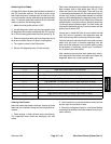
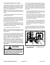
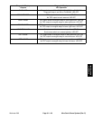
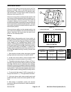
3. TheswitchterminalsareshowninFigure16.Thecir-
cuit logic of the sonic boom switch is shown in the chart
to the right. With the use of a multimeter (o hms setting),
theswitchfunctionsmaybetestedtodeterminewhether
continuity exists between the various terminals for each
switch position. Verify continuity between switch termi-
nals. Replace switch if testing identifies a faulty switch.
4. To test switch light, apply 12 VDC to terminal 8 (+)
and ground terminal 7 (--). The light should illuminate.
5. If the sonic boom switch tests correctly and circuit
problem still exists, check sonic boom system wire har-
ness.
6. After testing is completed, connect wire harness
connector to thesonic boomswitch. Installconsole pan-
el to machine.
1. Spray control panel 2. Sonic boom switch
Figure 15
1
2
Figure 16
BACK OF SWITCH
46
1
5
82
7
3
SWITCH
POSITION
CLOSED
CIRCUITS
OPEN
CIRCUITS
MANUAL 2+3
5+6
2+1
5+4
AUTOMATIC 2+1
5+4
2+3
5+6
Ultra Sonic
Boom System