


90
Dukane Manual Part No. 403–566–01
DPC
™
II Plus and EZ Welder System – User’s Manual
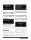
Limit Definition
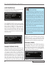
To access the Limit settings, start from the Pro-
cess Setup menu shown in Figure 8–1.
Select PROCESS LIMITS with the cursor and then
press ENTER. This displays the LIMIT DEFINITION
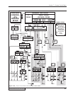
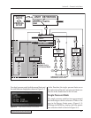
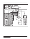
menu as shown in Figure 8–2. These steps are in-
dicated at the top of Figure 8–4 which is the flow
chart for the Limit Definition. Both the suspect
Limits and Bad Limits share the same logical
structure, so no distinction is made between them
in this flow chart.
Suspect & Bad Limits
You can select either a Suspect or Bad Part Limit.
A Suspect Limit allows the weld cycle to continue,
but causes an error indication in the display (> or
< for upper or lower limit). If a Bad Limit is
exceeded, the weld cycle is terminated, and an error
indication is displayed (>> or << for upper or lower
limit) until the next weld cycle is initiated. A bad
limit and suspect limit value share the same
memory location. To change a Suspect Limit value
to a Bad Limit value, move the cursor to BAD
PROCESS SETUP
PROCESS CONTROL
PROCESS LIMITS
UTILITIES
LIMITS in the Limit Definition menu and press
ENTER. The value is now associated with a Bad
Limit and will now terminate the weld cycle if the
measured value fall outside the boundary limits.
Process Limits
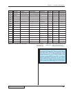
Select either Suspect Limits or Bad Limits and press
the ENTER key. The choice can be easily changed
later. The Process Limits menu is then displayed.
This is shown in Figure 8–3 as it would appear for
a single–pressure mode weld cycle.
LIMIT DEFINITION
SUSPECT LIMITS
BAD LIMITS
PROCESS LIMITS
TIME
ENERGY
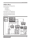
Figure 8–1 Process Setup Main Menu
Figure 8–2 Limit Definition Menu
Figure 8–3 Single–Pressure Process Limits Menu
LIMIT SELECTION
You normally select the alternate unit of mea-
surement for bad and suspect limits. If you are
welding by time (
Seconds), all the weld cycles
have the same weld time. There should be no
measurable deviation from the target time value.
There will however, be some variation in the
power drawn by each part. Since the time is con-
stant, the power and thus the energy will vary
slightly between parts. The limit check therefore
should be in units of energy
(Joules). Too low an
energy draw might result from a mechanical stop
interfering with travel. Too much energy drawn
may be caused by a misaligned part resulting in
a large mating surface area.
If you are using dual–pressure mixed mode, a
good limits check would set the companion limit
for each pressure plus the total time and en-
ergy limits. In a dual–pressure uniform mode,
only the alternate units for P1, P2 and TOTAL
will be meaningful.