


43
Dukane Manual Part No. 403–566–01
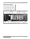
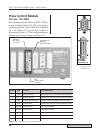
Section 5 – Rear Connectors
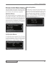
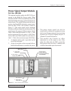
Output Signal Description
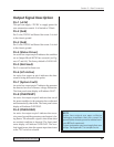
Pin 1 (+22V)
This pin can supply +22VDC to supply power for
user automation controls. It is limited to 250mA.
Pin 2 (Gnd)
Pin 2 is the 22VDC and Status Out return. It is tied
to the chassis ground.
Pin 3 (Gnd)
Pin 3 is the 22VDC and Status Out return. It is tied
to the chassis ground.
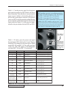
Pin 4 (Status Driver)
An active low output on pin 4 indicates the condition
set on Jumper Block SH702 has occurred (see Fig-
ures 4-7 and 4-8). The factory default is
OVERLOAD.
Pin 5 (Not Used)
Pin 5 is reserved for future use.
Pin 6 (U/S Active)
An active low output on pin 6 indicates the ultra-
sound is being delivered to the probe.
Pin 7 (System Fault)
An active low output on pin 7 indicates the generator
has detected an out of tolerance voltage fluctuation.
The front panel status display will indicate FAULT.
Pin 8 (OVERTEMP)
An active low output on pin 8 indicates that one of
the power modules in the generator has overheated
and automatically shut down. The front panel status
display will indicate OVERTEMP.
Pin 9 (OVERLOAD)
An active low output on pin 9 indicates that exces-
sive power beyond the generators rated output is be-
ing drawn. The ultrasonic signal is shut down when
an overload condition is detected. The front panel
status display will indicate OVERLOAD. The over-
load signal resets when the operate input deactivates
or the TEST switch is released.
NOTE
Active Low outputs are open collector
Darlington transistors that sink current to
ground (either chassis ground or isolated com-
mon @20mA maximum).
Custom automation users must supply their own
pullups. See Appendix C for sample circuits.