


19
Dukane Manual Part No. 403–566–01
Section 3 – Unpacking and Installation
Rear AC
Power Switch
Slave Multi–Probe
Controller Module
Master Multi–Probe
Controller Module
Press Control
Module
Power Signal
Output Module
Remote Amplitude
Control Module
EEPROM Serial
Programming Port
Grounding
Lug
Model No. Tag
Serial
No.
Tag
IEC
AC Power
Input
J1 Ultrasound
Output (BNC)
System
Input
Connector
System
Output
Connector
(DPC II Plus only)
(DPC II Plus only)
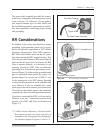
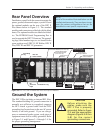
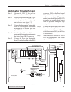
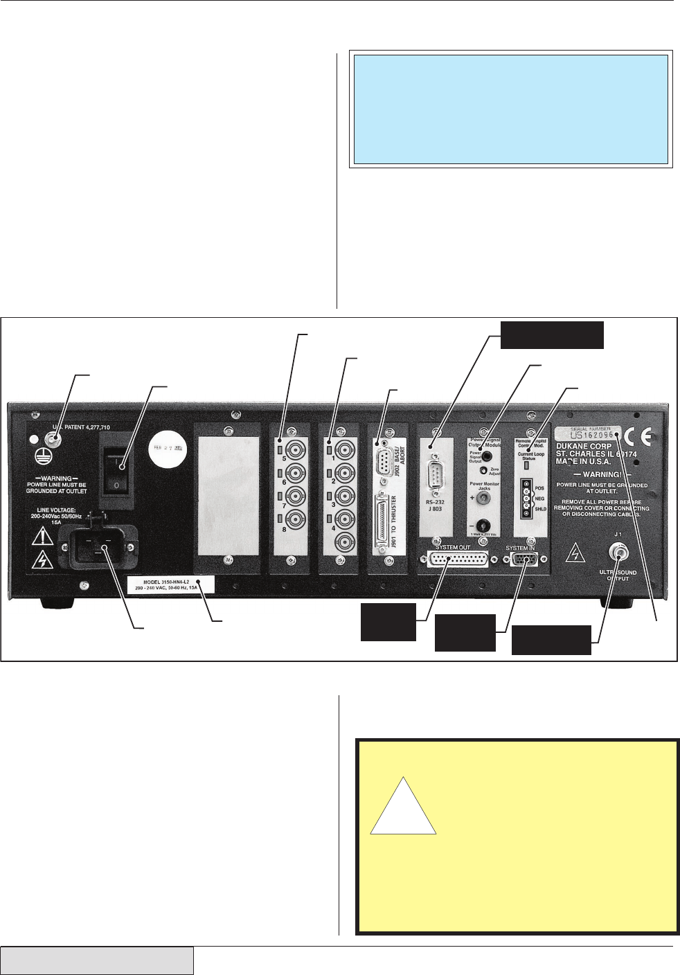
Rear Panel Overview
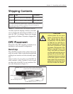
Familiarize yourself with the connection points for
power, ground, ultrasound output, system I/O and
the optional modules on the rear of the DPC II
Plus shown below in Figure 3–3. The standard
modules and connectors are labeled with the black
boxes. The optional modules are labeled with ital-
ics. The EEPROM Serial Programming Port is
used to upgrade the DPC™ firmware. The ground-
ing lugs, serial number tags, etc. are located in the
same position on all DPC II, EZ Welder, DPC II
Plus, DPC III and DPC IV generators.
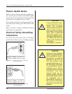
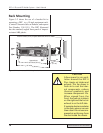
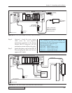
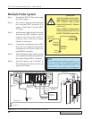
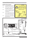
Ground the System
The DPC II Plus includes an internal RFI filter.
The standard building AC ground connection is
normally not sufficient to completely suppress
the RFI. Attach a ground cable from the DPC
grounding lug (located next to the rear AC power
switch) to an earth ground. If you are using a
press or automated probe system, each piece of
equipment must also be solidly grounded. Refer
to Figure 2–5 and Figures 3–4 through 3–8 for
the proper grounding arrangement.
Figure 3-3 DPC II Plus and EZ Welder Rear Panel and Optional Modules
CAUTION
Before attaching the
cables, make sure the
DPC II Plus is properly
grounded. Refer to Figure
2–5 and the appropriate
diagram (Figures 3–4 thru
3–8) for the correct
grounding connections.
Ꮨ
NOTE
Not all of the modules illustrated below can be
installed simultaneously. They are shown to rep-
resent the various configurations that can be
assembled to meet specific requirements.