


50
Dukane Manual Part No. 403–566–01
DPC
™
II Plus and EZ Welder System – User’s Manual
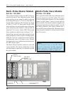
Multi–Probe Master Module
Part No. 110–3954
This optional module enables the DPC II Plus to
activate any one of four ultrasonic probes. Each
probe can have its own setup file which is selected
by the Setup ID# (pins 12, 13 & 14) of the HD–15
System Input connector. The functions are listed
in Table 5–I and 5–II. Rear panel bicolor LED
status indicators for each probe output illuminate
green when the probe channel is selected and red
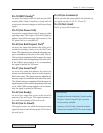
when the U/S is active. Both a MPC Master and
Slave module are shown below in Figure 5–10.
Internal logic prevents more than one probe from
being activated at a time or probe switching signals
when the U/S is on. A ring-down circuit permits
switching only when U/S output is zero. Internal
fault logic senses any malfunction and deactivates
the MPC Ready output.
The Multi–Probe Controller cannot be used with
a press module. The master module has an extra
wide back panel to prevent it’s accidental use with
the press module.
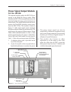
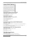
8 Ultrasound Outputs
(4 per Module)
Ultrasound
Input from J1
MPC Master
Module
P/N 110–3954
MPC Slave
Module
P/N 110–3956
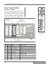
Multi–Probe Slave Module
Part No. 110–3956
This optional module adds four additional probe
selection channels to the DPC II Plus. This gives
a total of eight probe channels. The slave module
cannot be used alone. It must be used with the
master module. An internal connector supplies the
ultrasound signal from the Master module. As with
the Master module, each output channel has a
bicolor LED status indicator that illuminates green
when the probe channel is selected and red when
the U/S is active.
Figure 5–10 Master and Slave Multi–Probe Controller (MPC) modules
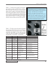
NOTE
The Ultrasound input on the MPC Master
must be connected to the DPC Ultrasound
output connector (J1) with a RG62B/U coax.
This is indicated as Cable 2 in Figure 3–6.