


49
Dukane Manual Part No. 403–566–01
Section 5 – Rear Connectors
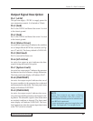
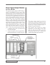
Table 5—V on the previous page lists the pinout
and signal description for J902 which is the Press
Base connection. Note that there is an automation
input on pin 8 which is electrically identical to
pin 8 on the System Input connector. This permits
you to use J902 to initiate operation without having
to run a separate connection to pin 8 of the System
Input connector. Figure 5–9 on the previous page,
identifies the pin numbers for both J902 and J901.
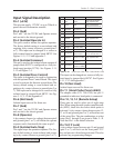
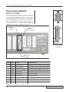
Table 5—VI below gives the pinout and signal
description for J901 which is the 36–pin Thruster
connector. This connector is the same type as found
on the DPC–III and DPC–IV. The cable specified
is Part No. 200–1104 which is interchangeable
with both DPC–III and DPC–IV generators.
Pin No. Input/Output Function Signal Type
13 Input Dual Pressure Switch
Normally–Open dry contact switch
closure to ground
14 Input Ground Detect
Normally–Open dry contact switch
closure to ground
15 Input Trigger Switch
Normally–Open dry contact switch
closure to ground
16 Input End Of Weld Switch
Normally–Open dry contact switch
closure to ground
Output Dual Pressure Valve Low side Mosfet driver to ground1
Output Trigger LED (–) Low side Mosfet driver to ground2
Ground +22V Return Power and Signal Ground
6, 8, 10, 12,
25, 27, 28, 29
30, 31, 32,34, 36
4, 19, 20,
22, 24, 26
Power +22V Press Internal Power to Press
7, 9, 11, 18
21, 23, 33, 35
Unused Unused Unused
Output Low side Mosfet driver to ground3 Up Valve
Output Low side Mosfet driver to ground5 Down Valve
17 Input
Normally–Open dry contact switch
closure to ground
Pre–trigger Switch
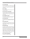
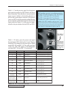
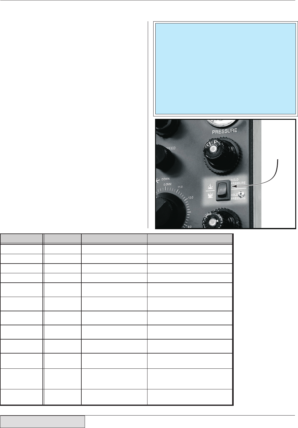
..connecting Dual
Pressure Press to
the Press Control
Module. This only
applies to the
DPC II Plus. The
EZ Welder System
is a single pres-
sure press.
Place switch in
WELD PRESSURE
position before..
Table 5—VI J901 Thruster Connector Pinout
NOTE
J902 Press Base connector has multiple ground pins.
The DPC–2 Plus/EZ uses pins 5, 6 & 7 for Ground.
The DPC–3 uses pins 5 & 7 for Ground.
The DPC–4 uses pins 6 & 7 for Ground.
To keep your custom automation circuits com-
patible with DPC models, only use pin 7 for a
ground connection to the Press Base connector.
It should be pointed out however, that the DPC–3
does have an Automation Input on pin 8.