


119
Dukane Manual Part No. 403–566–01
Section 11 – DPC Checkout
Startup and Self–Test
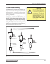
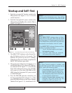
1. Push the rear panel AC breaker switch to the
ON position (see Figure 3–3 or 3–9 for the
switch location.)
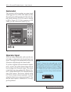
2. Push the front panel AC power switch to the
ON position (marked I on the switch.) This is
labled A in Figure 11–1.
3. The INPUT TEST indicator in the Status Dis-
play (B) flashes red for 5 to 10 seconds. This
indicates the power-up self test is running.
When the test has successfully completed, the
INPUT TEST indicator goes dark.
4. The green power indicator (C in Figure 11–1)
should then light up. The yellow OFF LINE sta-
tus indicator (D in Figure 11–1) should also
be lit. After subsequent power cycles, the DPC
will return to its last state (ON LINE or OFF
LINE
) when the front panel AC power switch
is turned ON again.
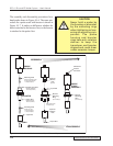
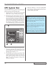
5. Press the ON LINE generator control key on
the front panel (labeled E in Figure 11–1.) The
green ON LINE indicator in the Status Display
(labeled F in Figure 11–2) should now be lit.
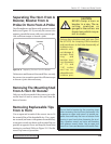
NOTE
If the INPUT TEST indicator does not flash,
check the AC line input. Both the rear panel
and front panel AC breaker switches must be
in the ON position, and the DPC line cord must
be properly connected to a live AC outlet.
If the INPUT TEST indicator flashes and then
remains in a steady red state –
1. The AC line level may be out of speci-
fied operating range.
2. The DPC may have an internal
fault preventing normal opertion.
NOTE
If either of the AC Breakers open, they will flip
the switch to its Off position marked by the O.
STATUS
FAULT
ON LINE
INPUT TEST
OVERTEMP
OVERLOAD
OFF LINE
ON
LINE
TEST
OFF
LINE
0
20 40 60
80 100
PERCENTAGE OF AVAILABLE POWER
PERCENTAGE OF AVAILABLE POWER
SYSTEM POWER OUTPUT
ẠẤạẢả
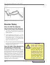
NOTE
If a Press Control module is installed, and
the ON LINE and OFF LINE indicators do not
light, check the follwoing items.
1. A Press Base cable (P/N 200–1124) must
be connected to J35 on the press and
J902 on the DPC (Cable 3 in Figure 3–8).
2. The Emergency Stop switch must be in
its reset position (pulled out).
3. In place of a press cable, a jumper block
(Dukane P/N 200–1293) can be
installed on J902 (see Figure 3–4).
Figure 11–1 Front Panel Startup Controls and Indicators