


158
Dukane Manual Part No. 403–566–01
DPC
™
II Plus and EZ Welder System – User’s Manual
Figure 10–1 Hand Probe, Horn and Replaceable Tip ........................................ 105
Figure 10–2 Probe with Booster and Horn .......................................................106
Figure 10–3 Replaceable Tip Installation ..........................................................107
Figure 10–4 Stack Assembly Procedure ............................................................109
Figure 10–5 Torque Value Conversion Graph ................................................... 110
Figure 10–6 Hand Probe Assembly and Disassembly ........................................111
Figure 10–7 Probe Stack With Booster Assembly and Disassembly ................... 112
Figure 10–8 Separating The Horn From The Booster ........................................113
Figure 10–9 Removing Replaceable Tip From Horn .......................................... 114
Figure 11–1 Front Panel Startup Controls and Indicators .................................. 119
Figure 11–2 System Test Controls and Indicators..............................................120
Figure 11–3 Stopping The Weld Cycle ............................................................. 121
Figure 12–1 Rear Ultrasound and System In Connectors ..................................125
Figure 12–2 Generator ON LINE Key and Indicator ........................................... 126
Figure 12–3 Troubleshooting Flowchart – Part 1 .............................................. 127
Figure 12–4 Troubleshooting Flowchart – Part 2 .............................................. 128
Figure 13–1 Location of DPC Air Cooling Vents ...............................................135
Figure 13–2 Location of Stack Mating Surfaces................................................ 136
Figure 13–3 Flat Surface With Even Contact ....................................................136
Figure 13–4 Surface With Uneven Contact ......................................................136
Figure 13–5 Crowned Surface .........................................................................135
Figure 13–6 Center Depression ........................................................................ 135
Figure 13–7 Manual Resurfacing......................................................................139
Figure 15–1 Generator 3–View and Dimensions .............................................. 148
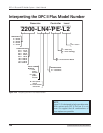
Figure 15–2 Interpreting the DPC II Plus Model Number .................................. 150
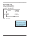
Figure C–1 Manual Control Switch.................................................................163
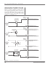
Figure C–2 Automation Control Switches ...................................................... 164
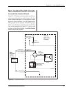
Figure C–3 Non–Isolated Current Sink Switch ................................................165
Figure C–4 Non–Isolated Current Source Switch ............................................166
Figure C–5 Isolated Current Source Circuit ..................................................... 167