


44
Dukane Manual Part No. 403–566–01
DPC
™
II Plus and EZ Welder System – User’s Manual
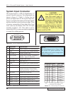
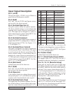
Pin 10 (ON LINE)
An active low output on pin 10 indicates the gen-
erator is on line and is capable of being triggered
externally. The front panel status display will indi-
cate
ON LINE.
Pin 11 (Gnd)
Pin 11 is the 22VDC and Status Out return. It is tied
to the chassis ground.
Pin 12 (Current Loop Fault)
1
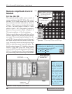
An active low output on pin 12 indicates the 4–20mA
current loop output has a fault. This output is only
available when a Remote Amplitude Control mod-
ule is installed.
Pin 13 (Monitor Gnd)
Pin 13 provides a return path to the chassis ground
for the monitor outputs on pins 14, 15 and 16.
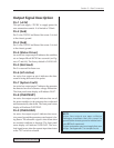
Pin 14 (Freq Out)
The signal on pin 14 is the actual output frequency.
It is a sine wave with an amplitude of 31Vrms maxi-
mum.
Pin 15 (Amp Out)
The signal on pin 15 is proportional to the output
signal amplitude. The scale is 10.0V = 100%. This
allows automation equipment to monitor the DPC
amplitude setting.
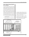
Pin 16 (Pwr Sig)
2
This output is only available when the optional Power
Signal Output module (part 438-826 ) is installed.
The signal on pin 16 is proportional to the true RMS
ultrasonic output power being drawn from the DPC.
The scale is 1mV = 1Watt on the 20kHz, 30kHz and
40kHz models. The maximum full scale output is
4.095V (4,095 Watts). On the 50kHz and 70kHz
models, the scale factor is 10mV = 1 Watt with a
maximum scaled output of 409.5 Watts.
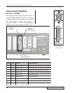
Pin 17 (Pwr Reg Status)
3
This option is not currently available.