


164
Dukane Manual Part No. 403–566–01
DPC
™
II Plus and EZ Welder System – User’s Manual
User Supplied
Relay
User Supplied
Transistor Driver
Circuit
HD–15
System Input
Connector
HD–15
System Input
Connector
HD–15
System Input
Connector
HD–15
System Input
Connector
Normally
Open
Contact
To
Automation
Control
Signal
To
Automation
Control
Signal
To
Automation
Control
Signal
To
Automation
Control
Signal
User Supplied
Opto-Coupler
User Supplied
Open-Collector
Darlington Driver
DPC Switch Input
DPC Ground
Ạ
ạ
Ạ
ạ
Ạ
ạ
Ạ
ạ
DPC Isolated Input 2 (Figure C–3) or
DPC Power Source (Figure C-4)
DPC Ground (Figure C–3) or
DPC Isolated Input 1 (Figure C–4)
DPC Isolated Input 2 (Figure C–3) or
DPC Power Source (Figure C-4)
DPC Ground (Figure C–3) or
DPC Isolated Input 1 (Figure C–4)
DPC Isolated Input 2 (Figure C–3) or
DPC Power Source (Figure C-4) or
DPC Ground (Figure C–3) or
DPC Isolated Input 1 (Figure C–4) or
DPC Isolated Input 2 (Figure C–3) or
DPC Power Source (Figure C-4)
DPC Ground (Figure C–3) or
DPC Isolated Input 1 (Figure C–4)
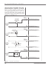
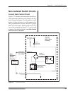
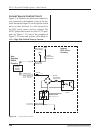
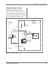
Automation Switch Circuits
Figure C–2 shows examples of various types of
user supplied automation control circuits con-
nected to the DPC Input. These examples can be
used in place of the low–side or high–side switches
in Figure C–3 and Figure C–4.
Figure C–2 Automation Control Switches