


31
Dukane Manual Part No. 403–566–01
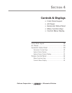
Section 4 – Controls & Displays
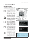
System Status Display
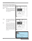
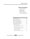
The System Status Display indicates one of the six
system states. If that state is active, the correspond-
ing label is lit in the display. Figure 4-4 shows the
System Status Display with the ON LINE state acti-
vated. The six status conditions are described here.
FAULT This indicator lights when out-of-toler-
ance voltage fluctuations occur that are
related to one of the following condi-
tions.
1. AC Line Voltage
2. Internal DC Power Supply (+5 VDC,
+12 VDC, -12V DC or +24V DC.)
INPUT TEST
This indicator normally flashes red dur-
ing a power-up test. If there is a prob-
lem, a steady red light appears. This
means that either the input AC line volt-
age is out of tolerance, or an internal
fault has occurred in the generator.
OVERLOAD
This red indicator lights when either of
the following conditions occur.
1. An instantaneous overload caused
by a mismatch between the ultrasonic
signal and the resonant characteristics
of the acoustic stack (transducer,
booster and horn.)
2. Excessive power beyond the
generator’s rated output is being drawn.
ON LINE The generator is capable of operation.
OVERTEMP
One of the power modules has over-
heated and the generator has shut down.
This may be caused by excessive dust
in the cooling channel or a cooling fan
failure. The generator will automatically
reset when the module temperature
drops below the trip point which is 75°C
(167°F).
OFF LINE The generator is in a standby mode. The
ultrasound output cannot be activated.
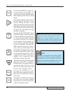
ON LINE OVERTEMP OFF LINE
FAULT INPUT TEST OVERLOAD
Figure 4–4 System Status Display