


42
Dukane Manual Part No. 403–566–01
DPC
™
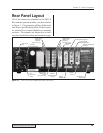
II Plus and EZ Welder System – User’s Manual
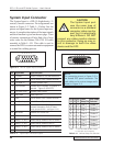
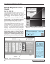
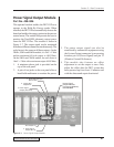
System Output Connector
The System Output panel connector is a DB-
25 Female type. Pin numbers are shown in Fig-
ure 5–4 and pin assignments are given in Table
5—IV. Dukane cable assembly P/N 200–1302
is used to connect the DPC to custom automa-
tion equipment to monitor the welding process.
A complete description of the signals and their
function is given on the following pages.
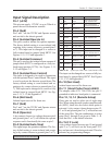
Table 5—IV System Output Connector Signals
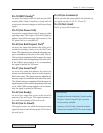
The System Output
port uses the same
type of connecor as
a standard RS-232,
DB-25 serial inter-
face, but it is
electrically very dif-
ferent. DO NOT
connect any RS-232
devices to this con-
nector. Doing so may
result in damage to
both the serial de-
vice and to the DPC
internal circuitry.
Ꮨ
CAUTION
Pin Signal Name Signal Description
+22VDC Current limited to 250 mA maximum
Gnd 22VDC Return (DPC Chassis Ground)
Gnd Status Driver Output Ground (DPC Chassis Ground)
Stat Drv Status Driver Output (1 amp maximum)
Not Used Spare Output Pin
U/S Active Ultrasound Status Output (Active Low)
Sys Fault System Fault Output (Active Low)
O T Fault Overtemperature Fault Output (Active Low)
O L Fault Overload Fault Output (Active Low)
10
On Line On Line Status Output (Active Low)
11
Gnd Status Outputs Ground (DPC Chassis Ground)
12
Loop Fault 4–20 mA Current Loop Fault Output
1
(Active Low)
13
Gnd Monitor Outputs Ground (DPC Chassis Ground)
14
Freq Out Frequency Monitor Output (31Vrms maximum)
15
Amp Out Amplitude Monitor Output (10.0V = 100%)
16
Pwr Sig Power Signal Monitor Output
2
(1mV = 1 watt)
17
Pwr Reg Stat Power Regulation Status Output
3
(Active Low)
18
MPC Ready Multi–Probe Controller Ready
4
(Active Low)
19
Iso Pwr Fail Isolated Power Fail Signal (Active Low)
20
Iso BSP Isolated Bad/Suspect Part Output
5
(Active Low)
21
Iso GP Isolated Good Part Output
5
(Active Low)
22
Iso RDY Isolated Ready Signal (Active Low)
23
Iso ID Isolated In–Dwell Signal (Active Low)
24
Iso Com Isolated Outputs Common (Isolated Gnd)
25
1
2
3
4
5
6
7
8
9
Not Used Spare Output Pin
13 12 11 10 9 8 7 6 5 4 3 2 1
25 24 23 22 21 20 19 18 17 16 15 14
Figure 5–4 DB-25 System Output Connector