


136
Dukane Manual Part No. 403–566–01
DPC
™
II Plus and EZ Welder System – User’s Manual
Top Cover
Keep the cover on at all times. The chassis is ro-
bust enough to hold considerable weight. How-
ever, avoid placing excessively heavy objects on
top of the chassis which may bend or dent the top
cover resulting in damage to internal components.
Replaceable Parts
The DPC is self contained and has no parts that
are replaceable by the user. If a part needs replace-
ment, contact your local Dukane representative.
See Section 14 for contact information.
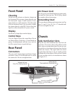
Stack Surfaces
Stack Maintenance
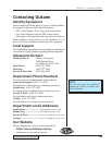
It is essential that the mating surfaces of the acous-
tic stack components be flat and smooth. When
the components are joined together and tightened,
there must not be any air gap between the surfaces.
If there is any air gap , there will be a loss in power
and efficiency. Air has much higher transmission
losses than the metal horn. Whenever the wavefront
encounters an air gap, the propagation velocity is
significantly reduced and attenuated. This results
in considerable loss. In some cases, the union be-
tween the mating surfaces could be so poor as to
prevent the probe stack from operating. This could
result in excessive power drawn from the genera-
tor and may damage the mating surfaces. Figure
13–2 shows the mating surfaces on a typical probe
and booster assembly.
Mating Surfaces
Stack Inspection
Examine the mating surfaces of the horn and probe
(and booster if applicable). Look for a shiny, bur-
nished area. This indicates where the surfaces have
been in contact. It will indicate whether the sur-
faces are flat and making good contact, or if they
are uneven and making poor contact.
Inspection Schedule
To establish a maintenance schedule, inspect the
mating surfaces after the first 200–400 hours of
operation. If they require cleaning, halve the next
inspection time. If the surfaces do not require re-
conditioning, then double the next inspection time.
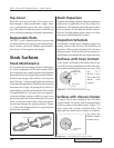
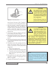
Surfaces with Even Contact
A flat surface will make even contact and its sur-
face will be evenly burnished across the entire con-
tact area. Fig-
ure 13–3
shows a sur-
face that has
made even
contact.
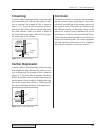
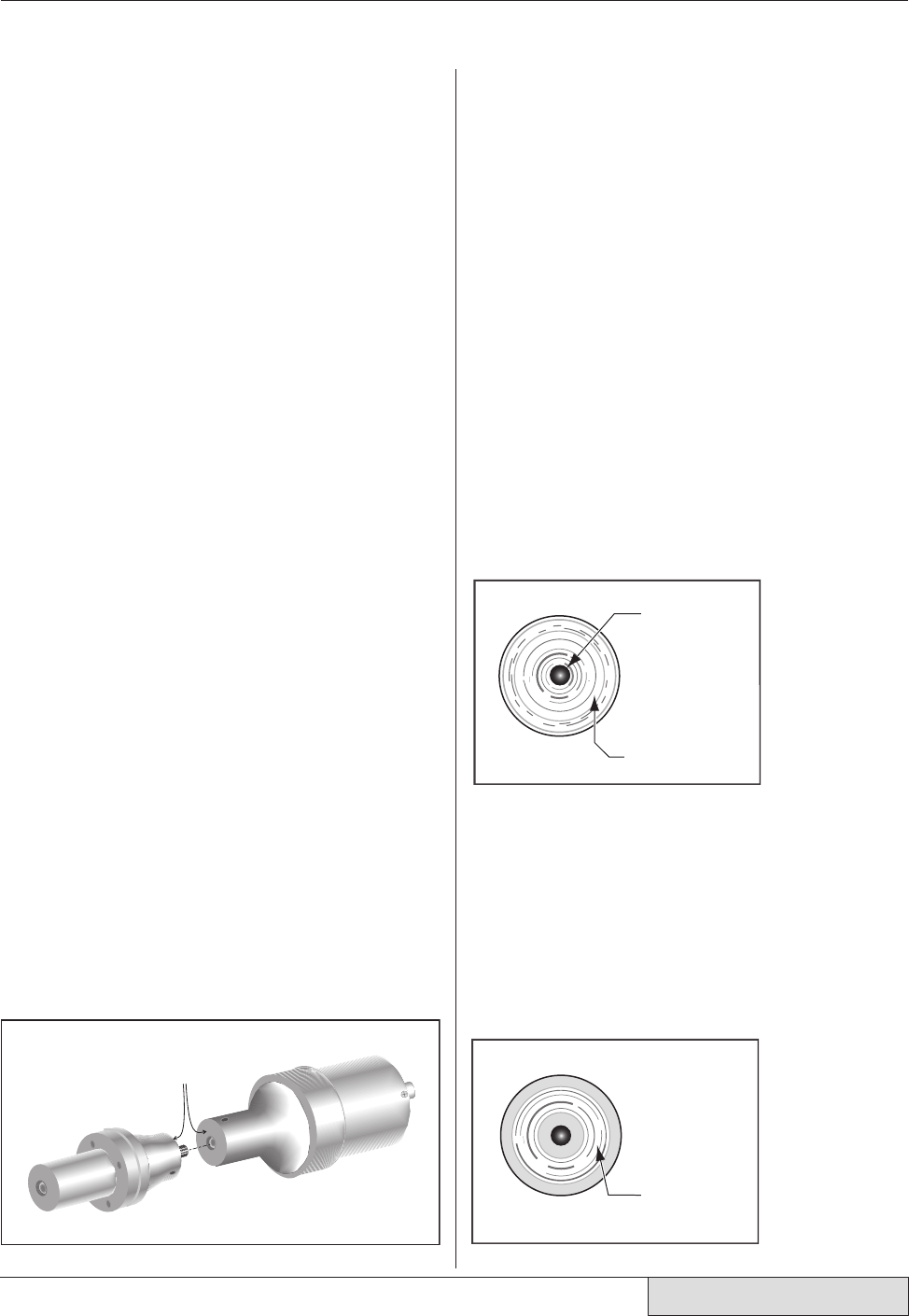
Surfaces with Uneven Contact
A surface that is not completely flat will make
uneven contact. Its surface will be burnished only
in the area where it has made contact. Figure 13–4
shows what such a surface would look like. The
inner and outer areas have no marks on it indicat-
ing there has
been no contact
in these areas.
Burnished
Area
Hole for
Mounting
Stud
}
Burnished
Area
}
Figure 13–2 Location of Stack Mating Surfaces
Figure 13–3 Flat Surface With Even Contact
Figure 13–4 Flat Surface With Uneven Contact