


114
Dukane Manual Part No. 403–566–01
DPC
™
II Plus and EZ Welder System – User’s Manual
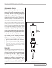
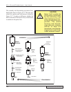
Booster Notes
How To Tell The Booster
Input End From The Output
1. The depth of the threaded hole on the output
end is always deeper than the threaded hole
on the input end.
2. On an amplifying booster (gain > 1.0), the
larger diameter end is the input end. On a re-
ducing booster (gain < 1.0) the larger diam-
eter end is the output end. On a neutral acting
booster the diameters are equal.
3. The cap screws on the booster mounting rings
are always inserted from the output end toward
the input end (see Figure 10–7).
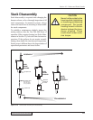
How To Tell If The Booster Is
Amplifying Or Reducing
Boosters have a die-stamped number on their sur-
face that indicates their gain or reduction. If the num-
ber is greater than 1.0 (e.g. 1.5), it is an amplifying
booster. If the number is less than 1.0 (e.g. 0.6), it is
a reducing or reverse booster. A neutral booster has
no gain and has 1.0 stamped on it. A neutral or cou-
pling booster is used to provide another probe stack
clamping location for added stability.
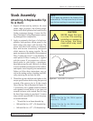
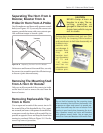
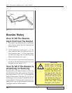
Loosen
Figure 10–9 Removing A Replaceable Tip From The Horn
ƽ
CAUTION
NEVER install a booster
upside down to change
an amplifying system to
a reducing system. The
boosters are dimension-
ally asymmetric. They are
tuned from input to out-
put to act like an acoustic
lens. Reversing them will
not give the expected re-
sults and may cause
damage to the system.