


74
Dukane Manual Part No. 403–566–01
DPC
™
II Plus and EZ Welder System – User’s Manual
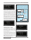
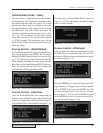
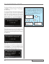
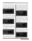
To select an afterburst, move the cursor down next
to ENABLE as shown in Figure 7–26 and press
the ENTER key.
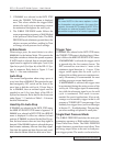
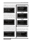
To setup the afterburst, the menu prompts you for
two parameter values. The first is the afterburst
delay. This is the delay after the start of the upstroke
before the burst starts. This data entry screen is
shown in Figure 7–27. Use the arrow keys to dis-
play the desired value and press the ENTER key.
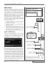
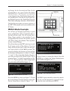
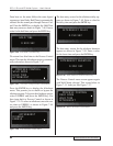
The menu now prompts you for the afterburst sig-
nal duration. This screen is shown in Figure 7–28.
Again enter the desired signal duration and press
the ENTER key.
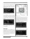
This returns you to the Process Control menu as
shown in Figure 7–22. Press the CANCEL key once
or the MODE key twice to return to the root Pro-
cess Setup menu shown in Figure 7–29.
AFTERBURST DELAY
0.150 SEC
AFTERBURST DURATION
0.300 SEC
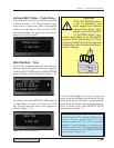
PROCESS SETUP
PROCESS CONTROL
PROCESS LIMITS
UTILITIES
Figure 7–27 Auto Probe Afterburst Delay Data Entry
Figure 7–28 Auto Probe Afterburst Duration Data Entry
Figure 7–29 Process Setup Menu
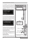
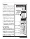
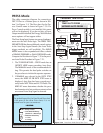
NOTE
The RTW symbol in the flow chart is signified
by the display of the
PROCESS CONTROL menu.
From the
PROCESS CONTROL menu, press the
MODE key twice or the CANCEL key once to re-
turn to the root
PROCESS SETUP menu.
PROCESS SETUP
PROCESS CONTROL
PROCESS LIMITS
UTILITIES
PROCESS CONTROL
WELD MODE
HOLD TIME
AFTERBURST
----- #1 TIME ENERGY
0.000 0
MODE
MODE
MODE
CANCEL