


41
Dukane Manual Part No. 403–566–01
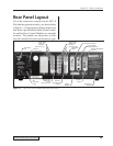
Section 5 – Rear Connectors
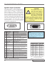
Input Signal Description
Pin 1 (+22V)
This pin can supply +22VDC at up to 250mA to
power the user's automation controls.
Pin 2 (Gnd)
Pin 2 and 7 are the 22VDC and Operate returns
and are tied to the chassis ground.
Pin 3 (Isolated Operate In)
This pin is used to initiate the operate sequence.
The factory default setting is a non-isolated sink
requiring a dry contact closure to ground (pins 2
or 7). This input can be changed to a source or
fully isolated input by jumper block SH707. See
Figures 5–11, 5–12 and Appendix C.
Pin 4 (Isolated Common)
This pin is used as the isolated return common if
jumper block SH707 is configured as a fully iso-
lated input (position JU726). See Figures 5–11,
5–12 and Figure C-5.
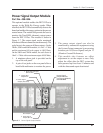
Pin 5 (Isolated Press Control)
This input is designed to be used in conjunction
with the optional Press Control Board. The signal
is used to activate the thruster up and down. The
factory default setting is a non-isolated sink re-
quiring a dry contact closure to ground (pins 2 or
7). This input can be changed to a source or fully
isolated input by jumper block SH707. See Fig-
ures 5–11, 5–12 and Appendix C.
Pin 6 (Not Used)
Isolated input reserved for future use.
Pin 7 (Gnd)
Pin 2 and 7 are the 22VDC and Operate returns
and are tied to the chassis ground.
Pin 8 (Operate)
A dry contact closure (no voltage) between pin 8
and ground (pins 2 or 7) will initiate the operate
sequence and is functionally the same as pin 3.
Pin 9 (Isolated Auto Stop)
This signal stops the operation sequence. The fac-
tory default setting is a non-isolated sink requir-
ing a dry contact closure to ground (pins 2 or 7).
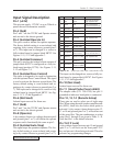
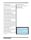
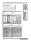
Table 5—III
System Input Cable Color Code (P/N 200–1203)
This input can be changed to a source or fully iso-
lated input by jumper block SH707. See Figures
5–11, 5–12 and Appendix C.
Pin 10 (Not Used)
Isolated input reserved for future use.
Pin 11 (Hand Probe Press Inhibit)
The adapter cable (P/N 200–1203) has pin 11
grounded to indicate a hand probe is connected.
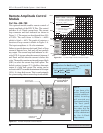
Pins 12, 13, 14 (Remote Setup)
These pins are used to select one of eight setup
files. When using the multi–probe controller mod-
ule (MPC), these bits also select which probe is
activated. A dry contact closure between pins 12,
13 or 14 and ground (pins 2 or 7) will activate one
of the setup files. The pin combinations to select
setup files 1 through 8 are given in Table 5—II.
Note that file 1 is the default selection.
Pin 15 (F P Lock)
A dry contact closure between pin 15 and ground
(pins 2 or 7) will lock out the front panel TEST
key and prevent it from being activated. This also
prevents any programming changes.
Pin Color Signal Desc Note
10
Blue Reserved
11
Orange/Blk
Hand Probe
Press Inhibit
Black may be faint –
Don't confuse with 9
13
Green/Blk
Remote Setup
Selection
14
Black/Wht
Remote Setup
Selection (MSB)
Black Gnd
Also connected to
connector metal shell
2
Blue/Blk Iso Oper In
3
Green/Wht Iso Common
4
Blue/Wht Iso Auto Cntrl
5
Orange
Iso Auto Stop
9
15
Green
F P Lock
+22V
Red used by Belden
may appear brown
1
Red
Reserved
Red used by Belden
may appear brown
6
Red/Blk
Gnd7
White/Blk
Sw Oper Input
8
White
12
Remote Setup
Selection (LSB)
Red used by Belden
may appear brown
Red/Wht