


89
Dukane Manual Part No. 403–566–01
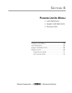
Section 8 – Process Limits Menu
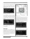
Process Limits Menu
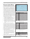
The Process Limits Menu allows you to define
upper and lower bounds for suspect parts or for
bad parts. The limits are available in both units
of time and units of energy depending upon the
welding method chosen in Process Control setup.
In addition, if a dual–pressure welding method
is selected, total time and/or total energy limits
are also available for suspect or bad parts. The
same memory location is used for suspect and
bad part limits. The difference is that exceeding
a bad part limit terminates the weld cycle. Ex-
ceeding a suspect limit allows the weld cycle to
continue until it finishes normally or exceeds a
Total limit. There are 12 different limit settings
which are broken down as follows:
1a. There are two possible
BAD PART UPPER TIME
LIMITS
(one for each pressure level).
1b. There are two possible BAD PART UPPER ENERGY
LIMITS
(one for each pressure level).
1c. There is one TOTAL BAD PA RT UPPER TIME LIMIT
and one TOTAL BAD PART UPPER ENERGY LIMIT.
This makes a total of six BAD PART UPPER
LIMITS
.
2. There are six BAD PAR T LOWER LIMITS.
During a dual–pressure mode welding cycle how-
ever, only six of the limits (eight in mixed mode)
are applicable. In single pressure mode, this drops
to two usable limits at any one time since the
totals are available only in dual mode. For ex-
ample, you can set both upper time and energy
limits, but only the upper time limit is recognized
in the weld by time mode.
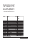
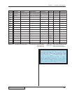
Table 8—I summarizes the 8 limits recognized in
a dual–pressure, mixed–mode welding cycle.
Table 8—II summarizes the 6 limits recognized in
a dual–pressure, uniform–mode welding cycle.
Table 8—III lists the 2 limits recognized in a single–
pressure welding cycle.
A Bad Parts Counter is also available in the Utili-
ties menu which is covered in the next section.
Cycle State Parameter Limit Type
P1 T(E)
U
P1 Upper TIME(ENERGY) Limit
P2 Upper E
NERGY(TIME) Limit
Total Upper T
IME Limit
Total Upper E
NERGY Limit
P1 Lower T
IME(ENERGY) Limit
P2 Lower E
NERGY(TIME) Limit
Total Lower T
IME Limit
Total Lower E
NERGY Limit
P2 E(T)
U
Total T
U
Total E
U
P1 T(E)
L
P2 E(T)
L
Total T
L
Total E
L
Cycle State Parameter Limit Type
P1 T(E)
U
P1 Upper TIME(ENERGY) Limit
P2 Upper T
IME(ENERGY) Limit
Total Upper T
IME(ENERGY) Limit
P1 Lower T
IME(ENERGY) Limit
P2 Lower T
IME(ENERGY) Limit
Total Lower T
IME(ENERGY) Limit
P2 T(E)
U
Total T(E)
U
P1 T(E)
L
P2 T(E)
L
Total T(E)
L
Cycle State Parameter Limit Type
P1 T(E)
U
P1 Upper T
IME
(E
NERGY
) Limit
P1 Lower T
IME
(E
NERGY
) LimitP1 T(E)
L
Table 8—I Recognized Limits in a Dual–Pressure
Mixed–Mode Welding Cycle
Table 8—II Recognized Limits in a Dual–Pressure
Uniform–Mode Welding Cycle
Table 8—III Recognized Limits in a Single–Pressure
Welding Cycle
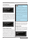
DEFINITION
A mixed mode is a dual–pressure weld cycle in
which one unit of measurement (e.g. time) is
used for Pressure 1 and the other unit of mea-
surement (e.g. energy) is used for Pressure 2.
A
uniform mode is a dual–pressure weld cycle in
which the same unit of measurement (e.g. time)
is used for both Pressure 1 and Pressure 2.