


126
Dukane Manual Part No. 403–566–01
DPC
™
II Plus and EZ Welder System – User’s Manual
Generator
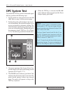
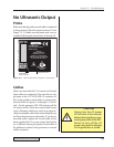
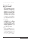
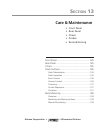
The generator will not produce an output signal
when triggered if it is OFF LINE. Make sure that
the green power indicator [A] is lit. The status dis-
play should indicate ON LINE which is marked
as [B] in Figure 12–2. If the generator is OFF
LINE, press the ON LINE control key [C].
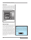
Operate Input
If you are using a hand probe, make sure the con-
trol cable is connected to the System Input con-
nector. The trigger on the hand probe activates the
Ultrasonic output through the control cable.
If you have supplied custom automation signals,
pin 8, or pins 3 & 4 of the Operate Input must be
used to trigger the Ultrasonic output. The system
control inputs are user configurable. Refer to Sec-
tion 5, Jumper Block SH707 for a detailed descrip-
tion of the options. The factory default setting
(JU724) is a contact closure to ground. If you are
using the isolated source jumper position (JU 726),
then the input requires a minimum of 5V to trig-
ger the generator.
STATUS
FAULT
ON LINE
INPUT TEST
OVERTEMP
OVERLOAD
OFF LINE
ON
LINE
TEST
OFF
LINE
0
20 40 60
80 100
PERCENTAGE OF AVAILABLE POWER
PERCENTAGE OF AVAILABLE POWER
SYSTEM POWER OUTPUT
Ạạ Ả
Figure 12–2 Generator ON LINE Key and Indicator
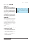
NOTE
Figure 5–3 shows the male cable end of the
System Input connector and is repeated here.
The cable end connector is a mirror image of
the female panel connector shown in Figure
5–2. Make sure you have correctly wired the
connector if you are using custom automa-
tion signals.
1 2 3 4 5
6
10
11 12 13 14 15