


47
Dukane Manual Part No. 403–566–01
Section 5 – Rear Connectors
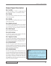
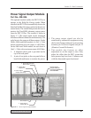
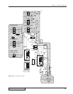
Power Signal Output Module
Part No. 438–826
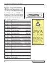
This optional module enables the DPC II Plus to
operate in the Weld–By–Energy mode. When
installed, the DPC II Plus automatically detects the
board and enables the energy options in the process
control menu. The module also permits the user to
monitor the True-RMS ultrasonic output power
from the DPC II Plus. The module is shown in
Figure 5–7. The output signal can be monitored
from three different connectors simultaneously. The
scale factor is the same on all three outputs. On the
20kHz, 30kHz and 40kHz models, it is 1mV = 1 Watt
and the maximum full scale output is 4,095 Watts.
On the 50kHz and 70kHz models, the scale factor is
10mV = 1 Watt with a maximum output of 409 Watts.
1. A miniature phone jack is provided on the
top of the rear panel.
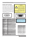
2. A pair of test jacks on the rear panel allow a
hand-held multimeter to monitor the power.
3. The power output signal can also be
monitored by automation equipment using
the System Output connector by measuring
between pin 16 (Power Signal) and pin 13
(Monitor Ground Reference).
4. This module also features an offset
adjustment to set the output to zero. Only
adjust the offset after the DPC system has
been powered up for at least 15 minutes and
with the ultrasound ouput deactivated.
Power Signal
Output Module
(
aka
Energy Module)
P/N 438–826
1. Power Signal Output
(Phone Jack)
3. Power Signal
Output (Pin 16)
Ground (Pin 13)
4. Output Zero
Adjustment
2. Power Signal
Output (Test Jacks)
Figure 5–7 Power Signal Output Module