


69
Dukane Manual Part No. 403–566–01
Section 7 – Process Control Menu
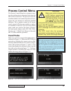
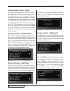
Untimed MPC Probe – Probe Delay
The probe delay time value for untimed operation
is shown in Figure 7–14. This parameter is typi-
cally used in a single auto probe configuration
which is covered later in this section. For MPC
untimed operation, the suggested value for the
delay time is 0.000 second.
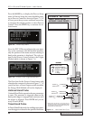
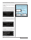
Weld Method – Time
For the Time welding method, an ultrasonic sig-
nal is generated for a specific time once triggered.
After the AUTO STOP menu, the WELD METHOD
menu is displayed. This is shown in Figure 7–15.
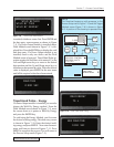
To weld by time, select WELD BY TIME using the
Up and Down arrow keys and press the ENTER
key. The weld time data entry screen appears as
shown in Figure 7–16.
PROBE DELAY
0.000 SEC
WELD METHOD
WELD BY TIME
WELD BY ENERGY
GROUND DETECT
WELD TIME
0.450 SEC
Use the Left and Right arrow keys to move the
cursor to the desired digit position and the Up and
Down arrow keys to increment or decrement the
value. When the desired value is displayed, press
ENTER to return to the main PROCESS SETUP
menu shown in Figure 7–5.
Figure 7–14 MPC Probe Time Delay
Figure 7–15 MPC Probe Weld Method Selection Menu
Figure 7–16 MPC Probe Weld Time
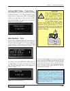
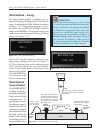
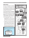
CAUTION
If the AUTO STOP option
is set to ENABLE, you
must supply the Isolated
Automation Stop input
signal to pin 9 of the HD–
15 SYSTEM INPUT con-
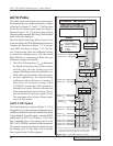
nector (see Table 5—I). The SH707
jumper block (see Figure 5–11) de-
termines whether the the signal is
isolated or non–isolated and sourc-
ing or sinking.
ƽ
NON-ISO SOURCE
NON-ISO SINK
JU724
JU725
JU726
ISOLATED
R771
C723
R772
C722
SH707
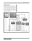
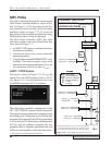
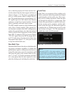
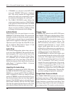
NOTE
The RTW symbol (RTW = Ready To Weld) at the
bottom of each logical branch in the
flowchart,means the DPC II Plus is logically
capable of being triggered to generate an
ultrasonic output. This is indicated on the display
screen by the presence of the
PROCESS SETUP
menu shown in Figure 7–5.