


57
Dukane Manual Part No. 403–566–01
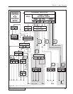
Section 6 – Menu Structure
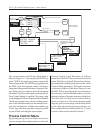
Process Setup Menu
This section deals with the overall menu structure.
Each setup menu is later discussed in detail in its
own section. Each time the DPC II Plus is powered
up, the processor scans the system to determine
which modules are installed and if a hand probe is
connected. It first displays which version of the
DPC firmware is installed as shown in Figure 6–1.
DUKANE DPC II+ v1.10
(c)2002 Dukane Corp.
All Rights Reserved
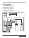
After a few seconds, the screen displays the welding
mode and installed modules. Depending upon your
configuration, your screen may display HAND PROBE
DETECTED, AUTO PROBE DETECTED, MPC PROBE DE-
TECTED, ECONOMY PRESS DETECTED.
or PRESS BOARD
DETECTED.
This is shown in Figure 6–2.
AUTO MODE
PRESS BOARD DETECTED
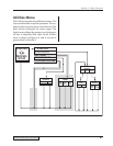
Then the screen then displays the operate page
which contains the measured values from the last
weld cycle as shown in Figure 6–3. If the Parts
Counter (covered in detail in Section 9 –Utilities)
is active, the count is displayed in the upper left–
hand corner in place of the dashes (– – – – –). The
# sign and the digit after the dashes indicate which
setup file is active. There are eight setup files avail-
able. Setup files are covered in Select Setup of
Section 9 – Utilities Menu.
–––––
#1 TIME ENERGY
P1 0.000 0
P2 0.000 0
TOTAL 0.000 0
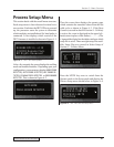
Press the MODE key once to switch from the
Operate mode to the Setup mode and display the
Process Setup menu shown below in Figure 6–4.
PROCESS SETUP
PROCESS CONTROL
PROCESS LIMITS
UTILITIES
Figure 6–2 DPC II Plus Configuration Menu
Figure 6–1 DPC II Plus Startup Menu
Figure 6–3 DPC II Plus Weld Cycle Display
Figure 6–4 DPC II Plus Process Setup Menu