75
Dukane Manual Part No. 403–566–01
Section 7 – Process Control Menu
PRESS Mode
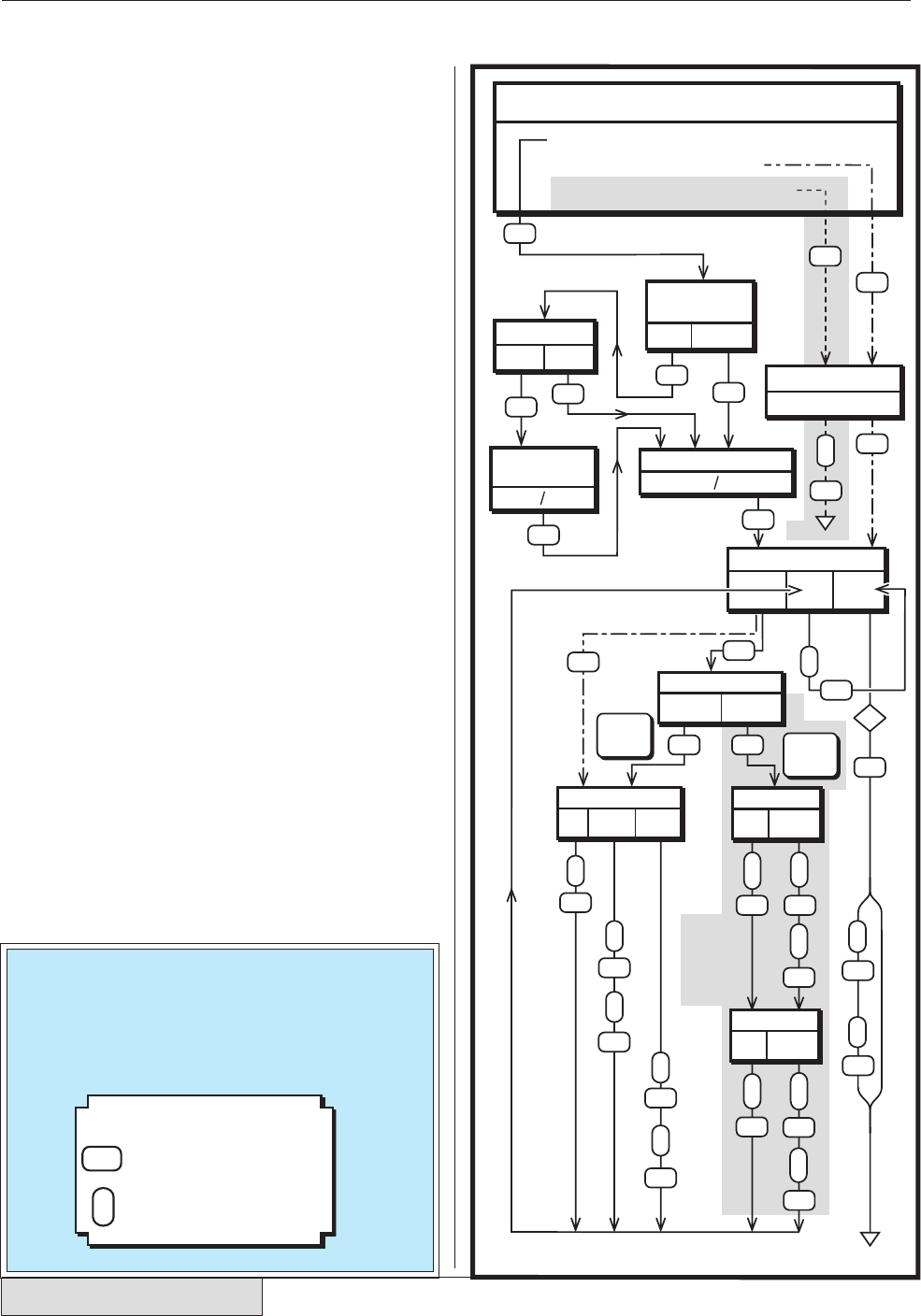
The cable connection diagram for connecting a
DPC II Plus to a Dukane press is shown in Sec-
tion 3 in Figures 3–8. The flow chart for the Pro-
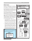
cess Control menu is shown in Figure 7–30. If a
Press Control module is not installed, this menu
will not be displayed. If you do not have a Power
Output module installed, the Energy Weld Method
menu options will not appear either.
The Press Setup logic features two areas of enhance-
ment over the Auto Probe logic. The PRESS TRIG-
GER METHOD
has three additional control options
in the Auto Stop logical branch (the Auto Probe
trigger methods are still available). The WELD
MODE
menu is also expanded and offers a choice
of SINGLE PRESSURE or DUAL PRESSURE mode.
Compare the flowchart in Figure 7–30 to the previ-
ous Auto Probe flowchart in Figure 7–21.
1. The TRIGGER METHOD – PRESS mode has an
INITIATE MODE menu preceding Auto Stop.
The MANUAL mode is the recommended set-
ting. This permits the dual palm switches on
the press base to initiate the operate sequence.
2. If ENABLE was selected in the AUTO STOP
menu, the HEAD UP ON AUTO STOP menu is
displayed. Auto Stop has been covered previ-
ously under MPC Probe and AUTO Probe. The
HEAD UP menu determines whether the press
head remains at its last position or retracts when
an external Auto Stop signal is detected.
PRESS
MANUAL
INITIATE
MODE
AUTO
MOMENTARY MAINTAINED
TRIGGER TYPE
WELD
MODE
11
22
HOLD
TIME
PROCESS CONTROL
AFTER–
BURST
Step 1
Timed
Auto
Probe
Bypasses
Single/Dual
Pressure
Mode
DPC II Plus
Models
Only —
Not Avail-
able on
EZ Series
Press Trigger
Method Only
Step 2
Step 3
RTW
AUTO STOP
ENABLE DISABLE
HEAD UP ON
AUTO STOP
WELD MODE
DUAL
PRESSURE
SINGLE
PRESSURE
WELD METHOD
TIME ENERGY
GND.
DETECT
PRESSURE 1
TIME ENERGY
PRESSURE 2
TIME ENERGY
ENABLE DISABLE
UNTIMED AUTO PROBE
TRIGGER METHOD
TIMED AUTO PROBE
ENABLE or DISABLE
AUTO STOP
RTW
E
/
D
ENTER
Enable/
Disable
ENTER
ENTER
ENTER
ENTER
ENTER
ENTER
ENTER ENTER
ENTER
ENTER
ENTER
ENTER ENTER
ENTER
ENTER
ENTER
ENTER
ENTER
ENTER
ENTER
ENTER
ENTER
ENTER
ENTER
ENTER
ENTER
ENTER
ENTER
ENTER
T
hold
T
weld
T
1
weld
E
weld
E
1
weld
E
2
weld
T
max
T
1
max
T
2
max
T
max
T
scrub
T
2
weld
T
delay
T
burst
T
delay
SINGLE
PRESSURE
PRESS
DUAL
PRESSURE
PRESS
Figure 7–30 Press/Auto Probe Setup Flow Chart
NOTE
The symbol legend for the Press Mode flow chart
is the same as the other flow charts. It is re-
peated here for your convenience.
T
weld
RTW
= Ready To Weld
LEGEND
= Front Panel ENTER Key
(Section 4.3 – Menu Keys)
ENTER
= Parameter Value Entry
T = Time
E = Energy


