


46
Dukane Manual Part No. 403–566–01
DPC
™
II Plus and EZ Welder System – User’s Manual
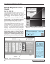
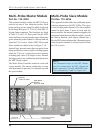
Remote Amplitude Control
Module
Part No. 438–799
This optional module enables remote control of
output amplitude of the DPC II Plus. The control
interface is a 4–20mA current loop. The current
loop connector and fault indicator are shown in
Figure 5–5. The output can be adjusted from 36%
to 100%. The scale factor is ∆16mA = ∆64%
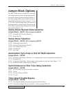
which is ∆1mA = ∆4%. The graph of output as a
function of loop current is shown in Figure 5–6.
The input compliance is 10 volts minimum.
Failure to provide between 4mA and 20mA of loop
current is detected as a fault and will not produce
any output. The current loop fault indicator is a bi–
color LED. It is green when the current is between 4
and 20mA and red when the current is below this
value. The module contains an internal jumper block
(SH1) to select the current loop fault option. The
default setting (jumper JU1) disables ultrasonic
output if a loop fault occurs The setting can be
reversed with JU2 to enable the minimum level output
(36%) if a loop fault occurs. This is used primarily
for system testing when a current loop is unavailable.
Remote Amplitude
Control Module
P/N 438–799
Current Loop
Fault Indicator
Current Loop
Connector
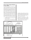
5mA0mA
20%
0%
40%
60%
80%
100%
10mA 15mA 20mA
4mA
Output
Disabled
JU1
Output
Enabled
Current
Loop
Fault
Region
36%
JU2
Out% = (20% + 4 I
Loop
)
%
Out% – 20
4
I
Loop
=
mA
75 – 20
= 13.75mA
4
20 + 4
x
8 = 52%
e.g. Determine
I
Loop
needed
for a 75%
Output
e.g. Determine %Output delivered
for an 8mA Loop Current
Figure 5–5 Remote Amplitude Control Module
Figure 5–6 Current Loop Transfer Function Graph
NOTE
The equations for Out% and I
Loop
are only valid
for normal operating conditions —
36% < Out% < 100% and
4mA < I
Loop
< 20mA
NOTE
If you have a Re-
mote Amplitude
Control module in-
stalled, its setting
will override any
front panel setting.
The front panel
menu will accept
the value, but the
output amplitude
will be determined
by the 4–20mA
loop current.