


163
Dukane Manual Part No. 403–566–01
Appendix C – User Supplied Circuitry
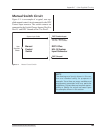
DPC Switch Input
DPC Ground
System Input Cable
Manual
Control
Switch
User
Supplied
Switch
Pin #8 – Operate or
Pin #15 – F P Lockout
Pin #2 or #7
DPC II Plus
HD–15 System
Input Connector
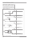
Figure C–1 Manual Control Switch
NOTE
The drawings and circuits shown in this sec-
tion are intended solely for purposes of
example. Since there are many variables and
requirements associated with any particular
installation, Dukane does not assume respon-
sibility or liability for actual use based upon
the examples shown in this section.
Manual Switch Circuit
Figure C–1 is an example of a typical, user sup-
plied manual control circuit connected to the DPC
Control Input conector. The switch contacts are
connected to the Switch Closure Input at Pin #8 or
Pin #15 and DPC Ground at Pin #7 or Pin #2.