


24
Dukane Manual Part No. 403–566–01
DPC
™
II Plus and EZ Welder System – User’s Manual
Ꮨ
Ꮨ
ƽ
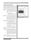
DUKANE CORP
ST. CHARLES, IL 60174
MADE IN USA
SERIAL NUMBER
US 10000
– WARNING! –
POWERLINE MUST BE GROUNDED
AT OUTLET
REMOVE ALL POWER BEFORE
REMOVING COVER OR CONNECTING
OR DISCONNECTING CABLES.
ULTRASOUND
OUTPUT
SYSTEM OUT
J901 TO THRUSTER
J902 BASE/
ABORT
+
–
Power Monitor
Jacks
Power Signal
Output Module
Power
Signal
Output
Zero
Adjust
SYSTEM IN
J1
U.S.PATENT 4,277,710
– WARNING–
POWER LINE MUST BE
GROUNDED AT OUTLET
LINE VOLTAGE
200–240Vac 50/60Hz
15A
MODEL NUMBER
200-240 VAC, 50-60Hz, 15A
Remote Ampltd
Control Mod.
Current Loop
Status
POS
NEG
SHLD
80–100 psi
Air Supply
J35
J1
J40
J3
Part No. 200–1124
Part No. 200–1104
Operational Control
8–conductor cable
Grounding Lug
Earth Ground
#14 Gauge
Wire
#14 Gauge Wire
#14 Gauge Wire
Coaxial Cable
RG62B/U
J901 to
Thruster
J902 to
Base/Abort
Part No. 200–479
110 VAC or
220 VAC
Grounding
Lug
Ultrasound Input
Ẅ
Ẅ
Ẅ
Ẉẇ
ẇ
Ẇ
Ẇ
ẅ
ẅ
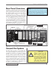
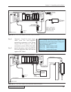
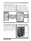
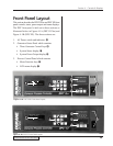
Dukane Press System
Step 1. Ground the DPC II Plus, the Thruster
and the Base as shown in Figure 3–8.
Step 2. Attach the high voltage coax cable
from the press J1 connector to the DPC
Ultrasound Out connector (J1).
Step 3. Connect the Press Base Input cable
from J35 on the Press Base to the DB-
9 connector (J902) on the Press
Control Module.
Step 4. Connect the Operational Control cable
from J3 at the top of the press to the
36–contact Thruster control connector
(J901) on the Press Control Module.
Step 5. Attach the power cord to the DPC II
Plus and plug the other end into an
approved AC outlet.
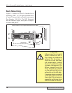
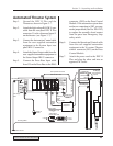
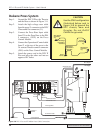
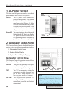
CAUTION
Use the STAR configuration
illustrated below and in
Figure 3–8 to ground the
DPC chassis, base and
thruster. Do not DAISY
CHAIN the grounds.
Ꮨ
Base/Fixture
Grounding
Lug
Earth
Ground
#14 Gauge
Stranded or
Solid Wire
#14 Gauge
Stranded or
Solid Wire
Thruster
Grounding
Lug
DPC Chassis
Grounding
Lug
Figure 3-8 DPC II Plus and EZ Welder Press Cable Connections