


25 – 3
Vission 20/20 • Operation and Service Manual •Vilter/Emerson • 35391SC 1.8.5153
Section 25 • Cool Compression Control
• Auto Load Timer
• This timer defi nes the maximum time that
the Auto Load operation will be engaged. After
the timer expires, Auto Load will be disengaged.
• Auto load will be disengaged when one of the follow-
ing conditions occur;
• Pressure ratio reaches a value of 2.0 or
greater.
• Compressor has been running for 10 minutes
(defi ned by Auto Load Timer).
• Suction pressure setpoint has been reached.
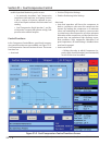
Suction Oil Injection Setting
• In order to maintain adequate lubrication during low
pressure ratio conditions, the Suction Oil Injection
(SOI) solenoid is turned ON and the capacity of the
compressor is reduced.
• The SOI solenoid will cycle ON and OFF based on the
pressure ratio across the compressor.
• SOI Solenoid ON
• Defi nes the Pressure ratio value at which
SOI is turned ON (default 2.00) (Digital Output
Board #1:2).
• SOI Solenoid OFF
• Defi nes the Pressure ratio value at which SOI
is turned OFF (default 2.04) (Digital Output
Board #1:2).
• SOI Load Limit
• Defi nes the capacity slide position at which
the compressor capacity slide will unload to if
pressure ratio falls below “SOI Solenoid ON” set-
point. This setpoint is not active until Auto Load
disengages.
• The SOI solenoid will also cycle on if the discharge
temperature superheat reaches a value of 5°F (this
value is not settable). Generally, anytime the SOI
solenoid cycles on, the capacity is limited to the SOI
Load Limit setpoint. However, this is not true if the
SOI solenoid cycles on based on the discharge tem-
perature superheat 5°F rule. If discharge temperature
superheat continues to climb and reaches a value of
6°F, the compressor will be inhibited from loading. If
discharge temperature superheat still continues to
climb and reaches a value of 8°F or more, then the
compressor will be unloaded until the superheat
drops below 8°F or the capacity has reached the SOI
Load Limit setting.
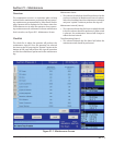
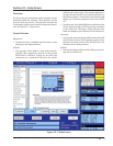
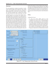
Using a Positioning Valve for Liquid Ammonia Level
Control
• A level probe inserted in the oil separator detects
liquid ammonia level. Based on the level of the am-
monia (0-100%), the level probe sends a directly pro-
portional 4-20 mA signal to the Vission 20/20 panel.
The positioning valve is then positioned based on the
Positioning Valve settings graph shown in Figure 25-
2. Cool Compression Control Functions Screen.
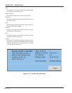
• Looking at the graph, when the compressor starts,
the positioning valve placement (Vertical Axis) is de-
termined based on the liquid ammonia level that is
sensed in the oil separator (Horizontal Axis). It can
be seen that as the liquid ammonia level increases
(corresponding to a larger mA value), the positioning
valve moves towards a closed position.
• The Positioning Valve position (0-100% limits) is de-
fi ned at three distinct levels;
• Start Level (lowest liquid ammonia level - po-
sitioning valve at maximum open position).
• Leakage (normal operating position and am-
monia level).
• Overfi ll Leakage (highest liquid ammo-
nia level–positioning valve at minimum open
position).
• Liquid ammonia levels are defi ned at four distinct lev-
els (4-20ma limits);
• Start SP (minimum liquid ammonia level in
separator – the positioning valve is maximum
open).
• Linear SP (minimum level of liquid ammonia
for normal operating position).
• Upper SP (maximum level of liquid ammonia
for normal operating position).
• Max SP (maximum liquid ammonia level – po-
sitioning valve is minimum open position, main-
taining some leakage).
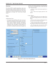
• On Alarms and Trips screen, Low Oil Separator Start
Temperature, High Filter Diff Start Pressure settings
are disabled.
• On Timers screen Oil Level #1 Safety Trip Delay, Oil
Level #2 Safety Trip Delay settings are disabled.
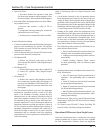
Operational Differences from Single Screw
Once the Cool Compression is confi gured, most setup
options available for a single screw are also available
for Cool Compression. However, there are signifi cant