


Vission 20/20 • Operation and Service Manual •Vilter/Emerson • 35391SC 1.8.5153
TOC - 1
Table of Contents
Section Title Section Number
How To Use This Manual ....................................................................................................................TOC-8
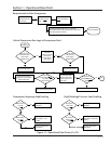
Section 1 • Operational Flow Charts
Requirements to Start Compressor ...................................................................................................1-1
Critical Compressor Run Logic at Compressor Start ...........................................................................1-1
Compressor Amperage Load Limiting ...............................................................................................1-1
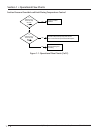
Figure 1-1. Operational Flow Charts ..................................................................................................1-1
High Discharge Pressure Load Limiting .............................................................................................1-1
Suction Pressure Override Load Limit During Temperature Control ...................................................1-2
Section 2 • Installation Recommendations
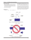
Proper Wiring Sizing .........................................................................................................................2-1
Voltage Source .................................................................................................................................2-1
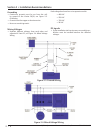
Figure 2-1. Vission 20/20 with Individual Transformer .......................................................................2-1
Figure 2-2. EMI and Vission 20/20 .....................................................................................................2-1
Grounding ........................................................................................................................................2-2
Mixing Voltages ................................................................................................................................2-2
DC signals .........................................................................................................................................2-2
Figure 2-3. Ground Wiring ................................................................................................................2-2
Figure 2-4. Mixed Voltage Wiring ......................................................................................................2-2
Wiring Methods ................................................................................................................................2-3
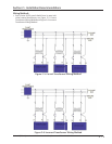
Figure 2-5. Correct Transformer Wiring Method ...............................................................................2-3
Figure 2-6. Incorrect Transformer Wiring Method .............................................................................2-3
Best Practices ....................................................................................................................................2-4
Section 3 • Hardware Architecture
Overview ..........................................................................................................................................3-1
Figure 3-1. Hardware Architecture Overview ....................................................................................3-1
Digital Input/Output (I/O) .................................................................................................................3-2
Table 3-1. Digital I/O .........................................................................................................................3-3
Analog Inputs ...................................................................................................................................3-4
Table 3-2. Analog Inputs....................................................................................................................3-5
Analog Outputs ................................................................................................................................3-6
Digital & Analog I/O Boards Layout ....................................................................................................3-6
Table 3-3. Analog Outputs.................................................................................................................3-7
Figure 3-2. Digital I/O Board Layout...................................................................................................3-7
Digital Outpout Boards .....................................................................................................................3-8
Figure 3-3. Digital Output Board Layout ............................................................................................3-8
Digital Input Boards ..........................................................................................................................3-9
Figure 3-4. Digital Input Board Layout ...............................................................................................3-9
Digital In-Out Boards ........................................................................................................................3-10
Figure 3-5. Digital Input-Output Board Layout ...................................................................................3-10
Analog Input Boards .........................................................................................................................3-11
Figure 3-6. Analog Input Board Layout ..............................................................................................3-11
Analog Input Jumper Tables ..............................................................................................................3-12
Table 3-4. Analog Input Jumper Tables ..............................................................................................3-12
Analog Output Boards ......................................................................................................................3-14
Figure 3-6. Analog Output Board Layout ...........................................................................................3-14