


6 – 7
Vission 20/20 • Operation and Service Manual •Vilter/Emerson • 35391SC 1.8.5153
Load Anticipating
The purpose of the load anticipating algorithm is to re-
duce the amount of overshoot of the capacity slide posi-
tion while the compressor attempts to meet the control
setpoint. This advanced feature of the Vission 20/20
closely monitors the rate of change of the process vari-
able and compares it to the control setpoint. If the pro-
cess variable is changing in the direction of the control
setpoint at the specifi ed rate or greater, then the normal
command to move the capacity slide is interrupted. The
rate is calculated between time intervals set in the pro-
portional control section of this screen.
Enable Load Anticipation Algorithm:
• Allows the operator to choose if the load anticipation
algorithm runs.
Rate Dead Band:
• Defi nes the rate at which the capacity slide move-
ment will be interrupted. This value is an absolute val-
ue of the process variable. For example, the default
value is 0.25. If the control mode is suction pressure,
then this value is 0.25 Psig or if process temperature
is the control mode then the value would be 0.25°F.
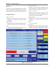
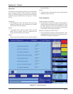
Oil Control
These setpoints determine how the Vission 20/20 will
manage the oil of the compressor.
Oil Pump Press Restart Ratio:
• The on and off setpoints defi ne when the oil pump
will cycle on and off if the oil pump is selected to cycle
from the confi guration screen.
Oil Separator Heater Temp:
• When the oil temperature falls below this setpoint
the oil heater will turn on. Note, there is a 5°F differen-
tial associated with this setpoint. For example, when
set at 100°F, the heater will turn on at 95°F and off at
105°F.
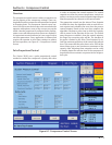
Liquid Injection
The setpoints is this section are to control the behavior
of the liquid refrigerant injected into the compressor for
oil cooling purposes. The liquid injection solenoid con-
trol is based off of discharge temperature whether the
compressor uses just an injection solenoid or a motor-
ized valve in conjunction with the solenoid.
Liquid Injection Solenoid Control ONLY
• When using only the liquid injection solenoid, the so-
lenoid is activated once the value of discharge tem-
perature meets or exceeds the value of “Liquid inj.
Setpoint 1” and the value of oil separator tempera-
ture meets or exceeds the value of “Oil Sep. Temp.
Override”. The injection solenoid will deactivate if
either of setpoints are not met. This will prevent situ-
ations where the discharge temperature may rise
quickly, but the oil temperature is still very cold. By
preventing the liquid injection solenoid from turning
on at this point, the oil separator will not be subjected
to additional liquid refrigerant, that would cool the oil
even further.
Liquid Injection Control using a 4-20ma motorized valve.
• When a motorized valve is used to control the amount
of liquid being injected into the compressor the pre-
viously mentioned setpoints have a slightly different
function. The Oil Sep. Temp. Override is still used in
controlling the injection solenoid, however the Liquid
Inj. Setpoint 1 is now used as the target temperature
for the PID Algorithm that controls the position of
the motorized valve. The algorithm compares the
actual discharge temperature against the Liquid Inj.
Setpoint 1. The difference between these is the error.
The PID algorithm tries to drive the error to “zero” by
moving the positioning valve to allow more or less
liquid refrigerant to be injected into the compressor.
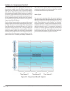
• PID algorithm can be notoriously hard to tune. As
a result the Vission 20/20 offers a couple of addi-
tional features to help control wild fl uctuations in
oil temperatures that could result in the compres-
sor tripping off. The operator can choose to enable
the minimum value position that automatically sets
the liquid injection motorized value to the specifi ed
value whenever the discharge temperature has fallen
below the Liquid inj. Setpoint 1. This feature nearly
eliminates the overshoot of the PID in the downward
direction and reduces the chance of the compressor
tripping off due to low oil temperature. The operator
can also choose to use an average of the discharge
temperature and the oil manifold temperature as the
control variable. The discharge temperature can vary
quite drastically forcing the PID algorithm to drasti-
cally adjust the motorized value. By averaging the
more stable oil manifold temperature and discharge
temperature, the control variable stabilizes and the
PID is more easily tuned.
• Please note that as stated above, PID algorithms can
be diffi cult to tune and there is no one set of PID val-
ues that will work. The work required for a compres-
sor to meet the requirement of its installation vary
greatly and therefore the amount of heat transfered
to the oil varies just as greatly. We recommend the
Section 6 • Compressor Control