


14 – 3
Vission 20/20 • Operation and Service Manual •Vilter/Emerson • 35391SC 1.8.5153
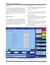
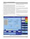
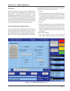
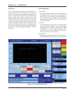
4. From the main screen select the Menu button.
5. On the menu screen select the Slide Calibration but-
ton. When the “Slide Valve Calibration” screen appears,
then you can safely connect the Power Cable (Yellow
TURCK cable) and the Position Transmitter Cable (Gray
TURCK cable) to the Capacity motor. Press “+” or “-” to
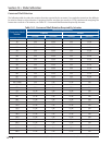
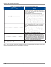
move the slide valves to check the rotation. (See Table 1
below for proper shaft rotation). If for any reason the “+”
or “-” command on the panel does not correspond to the
slide increase or decrease, swap the blue & brown wires
of the Yellow TURCK cable in the control panel to reverse
the rotation of the motor.
CAUTION
DO NOT CONTINUE TO ENERGIZE THE ACTUATO
R
MOTOR AFTER THE SLIDE HAS REACHED THE
MECHANICAL STOP. Doing so may cause mechanical
damage to the motor or shear the motor shaft
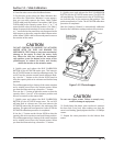
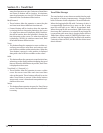
key. When the slide has reached the mechanical
stop position, press the button in the center of the
photochopper to release the brake, and thereby
release the tension on the actuator motor.
6. Quickly press and release the BLUE CALIBRATION
BUTTON on the ACTUATOR motor once. This instructs
the ACTUATOR motor to enter the calibration mode. The
red LED on the actuator control board will begin fl ash-
ing. Use the “-” button on the Vission 20/20 panel to
drive the capacity slide to its minimum mechanical stop
position.
This will be apparent by a slowing of the motor rotation
and a winding sound from the actuator motor. When
you hear the motor wind-up, release the “-” button.
Then use the “+” button to pulse the motor so that the
capacity slide is “just off” of its minimum position and
there is no tension on the motor shaft.
7. Quickly press and release the BLUE CALIBRATION
BUTTON on the ACTUATOR motor once. The red LED
will now fl ash at a slower rate. This now instructs the
ACTUATOR motor that this point is the minimum slide
position. This point will correspond to 0 volts AFTER the
ACTUATOR calibration procedure is completed.
8. Use the “+” button on the Vission 20/20 to drive the
capacity slide to its maximum mechanical stop position.
This will be apparent by a slowing of the motor rotation
and a winding sound from the actuator motor. When
you hear the motor wind-up, release the “+” button.
9. Quickly press and release the BLUE CALIBRATION
BUTTON on the ACTUATOR motor once. The RED LED
will stop fl ashing. This now instructs the ACTUATOR mo-
tor that this point is the maximum slide position. This
point corresponds to 5 volts. The ACTUATOR calibration
procedure is completed.
Now the Capacity Channel is automatically calibrated
based on the calibration settings made to the actuator.
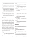
Figure 14-2. Photochopper
CAUTION
Do not over tigten screws. Failure to comply may
result in damage to equipment.
.
10. Gently lower the plastic cover to where it contacts
the base and O-ring seal. After making sure that the
cover is not binding, gently tighten the four # 10 Phillips
screws.
11. Repeat the same procedure for the Volume slide
motor.
Section 14 • Slide Calibration