


14 – 2
Vission 20/20 • Operation and Service Manual •Vilter/Emerson • 35391SC 1.8.5153
mechanical stops for normal slide travel. These soft-
ware limits purpose is to prevent the slide from actu-
ally hitting the mechanical stops which could result
in a number of undesirable consequences. By default,
the software limits are set to 150mV from either end
point. The position percentage is calculated from the
software limits. Therefore, it is possible to read a val-
ue greater than 100% or less than 0% if inertial carries
the slides after these limits are reached.
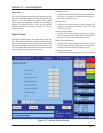
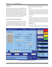
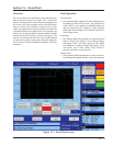
Volume Slide Valve Potentiometer
• This section provided critical information and con-
trol parameters related to the volume slide actuator.
The “% Vol” display shows the actual value in percent
of the volume slide with out any conditioning that
might be applied to the other volume position dis-
plays. In addition, this section displays the value of
the actuator signals in millivolts in the “input Value”
display box.
“-” Button:
• When the operator presses and holds this button,
the output associated with volume slide decreases
is energized. If the actuator does not turn in the cor-
rect direction when this button is pressed, then the
operator will have to alter how the actuator is wired
to the panel.
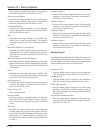
“+” Button:
• When the operator presses and holds this button,
the output associated with volume slide increase is
energized. If the actuator does not turn in the cor-
rect direction when this button is pressed, then the
operator will have to alter how the actuator is wired
to the panel.
Software limit setpoint:
• The Vission 20/20 uses the “Min Limit” and “Max
Limit” setpoint to defi ne an area within the mechani-
cal stops for normal slide travel. These software limits
purpose is to prevent the slide from actually hitting
the mechanical stops which could result in a number
of undesirable consequences. By default, the soft-
ware limits are set to 150mV from either end point.
The position percentage is calculated from the soft-
ware limits. Therefore It is possible to read a value
greater than 100% or less than 0% if inertial carries
the slides after these limits are reached.
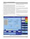
Slide Valve Operation
The slide valve actuator is a gear-motor with a position
sensor. The motor is powered in the forward and reverse
directions from the main computer in the control panel.
The position sensor tells the main computer the position
of the slide valve. The main computer uses the position
and process information to decide where to move the
slide valve next.
During calibration, the position sensor records the high
and low count of motor turns. The operator tells the
position sensor when the actuator is at the high or low
position with the push button. Refer to the calibration
instructions for the detailed calibration procedure.
The position sensor can get “lost” if the motor is moved
while the position sensor is not powered. To prevent
this, the motor can only be moved electrically while
the position sensor is powered. When the position sen-
sor loses power, power is cut to the motor. A capaci-
tor stores enough energy to keep the position sensor
circuitry alive long enough for the motor to come to a
complete stop and then save the motor position to non-
volatile EEPROM memory. When power is restored, the
saved motor position is read from EEPROM memory and
the actuators resumes normal function This scheme is
not foolproof. If the motor is moved manually while the
power is off or the motor brake has failed, allowing the
motor to free wheel for too long after the position sen-
sor looses power, the actuator will loose its calibrated
position.
A brake failure can sometimes be detected by the po-
sition sensor. If the motor never stops turning after a
power loss, the position sensor detects this, knows it will
be lost, and goes immediately into calibrate mode when
power is restored.
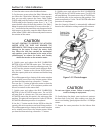
Slide Valve Actuator Calibration for Optical
Style Motors
Assuming that the actuator motors have not been cali-
brated, the transmitter output of the actuator motor
will fl uctuate wildly until they are calibrated. To prevent
damage to actuator motors, do not connect the Power
Cable (Yellow TURCK cable) or the Position Transmitter
Cable (Gray TURCK cable) until instructed to do so in this
procedure.
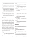
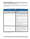
1. Open the plastic cover of the capacity motor by re-
moving the four #10 Pan Head Phillips screws. Gently lift
the cover and tilt it toward the TURCK connectors. Raise
the cover enough to be able to press the blue calibrate
button and to be able to see the red LED on the top of
the assembly, see Figure 14-2. Photochopper.
2. Remove actuator motor cover(s).
3. Log In on the Vission 20/20.
Section 14 • Slide Calibration