


3 – 14
Vission 20/20 • Operation and Service Manual •Vilter/Emerson • 35391SC 1.8.5153
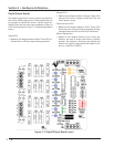
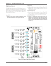
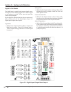
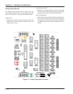
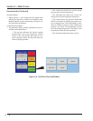
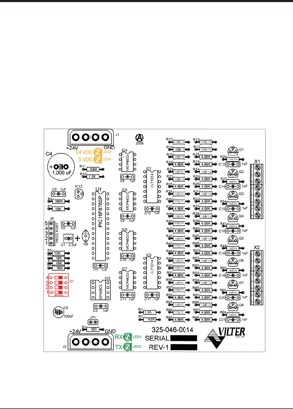
Analog Output Boards
The Analog Output board convert signals form the
Vission 20/20 program into a current ranging from 4mA
to 20mA, see Figure 3-7. Analog Output Board Layout.
Voltage LEDs:
• Marked in the diagram below in Orange. These LEDs
indicated the correct voltage of both the 5Vdc and
24Vdc power sources.
Communication LED’s:
• Marked in the diagram below in Green. These LEDs
show the active communications between the digital
output board and the Vission 20/20 CPU board.
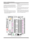
Address Dipswitches:
• Marked in the diagram below in Red. These dipswitch-
es are used to assign each board its address position.
The addresses are binary and therefore the address
of a digital output board will only be addressed as 10
(1010).
Figure 3-7. Analog Output Board Layout
Section 3 • Hardware Architecture