


14 – 7
Vission 20/20 • Operation and Service Manual •Vilter/Emerson • 35391SC 1.8.5153
Slide Valve Actuator Troubleshooting Guide Blink Code
Vilter actuators communicate problems discovered by the internal diagnostics to the technician by LED blink codes.
Only one blink code is displayed, even though it is possible that more than one problem has been detected. The actua-
tor motor will not operate until the error code is cleared by pressing the blue bottom, see Table 14-3. LED Blink Codes
and Troubleshooting Guide.
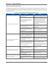
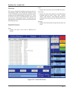
Table 14-3. LED Blink Codes and Troubleshooting Guide (1 of 2)
Flash Pattern
* = ON - = OFF
Meaning
*-*-*-*-*-*-*-*-*-*-*-*-
Calibration step 1.
*---*---*---*---*---*---
Calibration step 2.
*--*--------------------
This indicates a zero span. This error can only occur dur-
ing calibration. The typical cause is forgetting to move
the actuator when setting the upper limit of the span.
If this is the case, press the blue button to restart the
calibration procedure. This error can also occur if either
or both of the slotted optocouplers are not working. If
this is the case, the slide valve actuator will have to be
replaced.
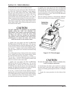
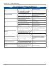
The operation of the slotted optocouplers can be tested
as follows:
1. Manually rotate the motor shaft until the aluminum
photochopper fence is not blocking either of the opto-
coupler slots.
2. Using a digital multimeter, measure the DC voltage
between terminal 3 of the small terminal block and TP1
on the circuit board (see Note 1). The measurement
should be between 0.1 and 0.2 Volts.
3. Next, measure the DC voltage between terminal 3
and TP2 on the circuit board. You should measure be-
tween 0.1 and 0.2 Volts.
*-----------------------
A motor over-speed occurred. At some time during
operation, the motor armature spun too fast for the
encoder to measure. A nonfunctional motor brake is
usually to blame. This error means that the slide valve
actuator is no longer transmitting accurate position
information. The actuator should be recalibrated as
soon as possible, after the cause of the over-speed is
identifi ed and corrected. This error will not clear until
the actuator is re-calibrated.
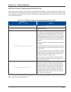
Note 1: TP1 and TP2 are plated-thru holes located close to the slotted optocouplers on the board. They are clearly
marked on the board silkscreen legend.
Section 14 • Slide Calibration