


3 – 2
Vission 20/20 • Operation and Service Manual •Vilter/Emerson • 35391SC 1.8.5153
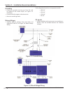
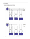
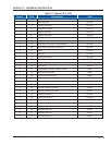
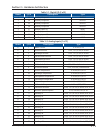
Digital Input/Output (I/O)
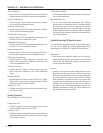
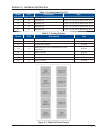
Refer to Table 2-1. Digital I/O.
Compressor Start Output:
• When the Vission 20/20 signals the compressor to
start, this output is energized. When the Vission
20/20 signals the compressor to stop, this output is
de-energized.
Oil Pump Start Output:
• When the Vission 20/20 signals the oil pump to start,
this output is energized. When the Vission 20/20 sig-
nals the oil pump to stop, this output is de-energized.
Capacity Increase Output:
• This output is only active when the compressor is
running. When the Vission 20/20 determines that
the compressor should increase capacity by moving
the slide valve to a higher percentage, this output is
energized. Once the slide valve reaches 100%, this
output will not energize.
Capacity Decrease Output:
• This output is only active when the compressor is
running. When the Vission 20/20 determines that
the compressor should decrease capacity by moving
the slide valve to a lower percentage, this output is
energized. Once the slide valve reaches 0%, this out-
put will not energize.
Volume Increase Output:
• This output is only active when the compressor is
running. When the Vission 20/20 determines that
the compressor should increase Volume Index (VI) by
moving the volume slide to a higher percentage, this
output is energized. Once the volume slide reaches
100%, this output will not energize.
Volume Decrease Output:
• This output is only active when the compressor is run-
ning. When the Vission 20/20 determines that the
compressor should decrease Volume Index (VI) by
moving the volume slide to a lower percentage, this
output is energized. Once the volume slide reaches
0%, this output will not energize.
Oil Sump Heater Output:
• This output is active and energized when the oil
separator temperature is lower than the oil separator
temperature setpoint. It is de-energized when the oil
separator temperature is higher than the oil separa-
tor temperature setpoint.
Trip Output:
• This output is energized when the system has no
Trips. If a trip is issued, the output de-energizes and
stays de-energized until the trip condition is cleared.
Slide Valve Setpoint #1 Output (Economizer):
• Normally used for an economizer solenoid, but could
be used for other devices. When the compressor slide
valve percentage is equal to or greater than “slide
valve set-point #1”, the output is energized. When
the compressor slide valve percentage is less than
“slide valve set-point #1”, the output is de-energized.
Slide Valve Setpoint #2 Output (Hot Gas):
• Normally used for a hot gas solenoid, but could be
used for other devices. When the compressor slide
valve percentage is equal to or greater than “slide
valve set-point #2”, the output is energized. When
the compressor slide valve percentage is less than
“slide valve set-point #2”, the output is de-energized.
Alarm Output:
• This output is energized when the system has no
alarms. If an alarm is issued, the output de-energizes
and stays de-energized until the alarm condition is
cleared.
Unused:
• This output has no current function.
Liquid Injection #1 Output:
• If the compressor has liquid injection oil cooling, this
output is active. When the compressor is running and
the discharge temperature is above the oil separator
temperature override setpoint and the oil separator
temperature is above the override setpoint, then the
output is energized. The output is de-energized when
the discharge temperature falls below the “on” set-
point minus the solenoid differential.
Liquid Injection #2 Output:
• Not Defi ned
Remote Enabled Output:
• This output is energized when the Vission 20/20
panel is enabled for remote control. The compres-
sor can be running or stopped, but is available to the
remote system. If the compressor has an alarm or is
placed into the manual stop position, this output is
de-energized.
Shunt Trip:
• Not defi ned.
Comp Motor Starter Auxiliary Contact:
• This input looks for a feedback signal from the com-
pressor starter, confi rming that the compressor
starter is energized.
Section 3 • Hardware Architecture