


13 – 2
Vission 20/20 • Operation and Service Manual •Vilter/Emerson • 35391SC 1.8.5153
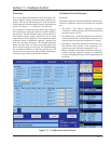
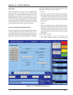
devices are predefi ned and if one is selected, then all
the setpoints will be set for the operator.
Custom Device:
• This option allows the operator to choose the mini-
mum and maximum value of the instrument being
used.
Offset:
• Once the two point calibration is completed, it is not
uncommon for there to be a small error. By entering
the value of the error from the calibrated value and
the actual value into the adjustment entry box, that
error will be added/subtracted from the total offset.
The offset is applied to the calibrated value which
should correct the error.
Range:
• This option is available when the custom device op-
tion is chosen. Here the operator defi nes the signal
type and range transmitted by the instrument. The
operator can choose from several predefi ned ranges
in the drop-down box or enter a value.
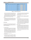
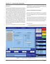
Motor Current
The Vission 20/20 has two options for measuring motor
current. A 4-20mA signal transmitted from an external
device or a 0-5Amp AC current Transformer. The type of
device being used is selected in the confi guration screen.
The motor current tab has the ability to calibrate both
measurement options through the 4-20mA scale and
current transformer ratio sections. However, the device
type that is selected in the confi guration screen will be
the only section that will be available to the operator.
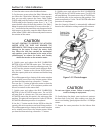
The calibration differs from all other calibration proce-
dures in that the motor current must be calibrated while
the compressor is running at close to full load amps as
possible. In addition, the operator will need to enter a
value into the “Enter Desired Value” entry box that is
equal to the measured value in amps by a calibrating
measurement device. After entering the measured val-
ue, the displayed motor current may still be off slightly.
In this case reenter the desired value and the displayed
value should get progressively closer.
4-20mA Scale:
• 4mA:
• Not editable by the operator. Defi nes the
minimum value in amps represented by a 4ma
inputs.
•
• 20mA:
• Defi nes the maximum value in amps repre-
sented by a 20ma inputs.
• Enter Desired Value:
• The operator enters the correct current value.
Each entry will recalculate the point-slope calcu-
lations of the current calibration.
• Total Error:
• Not editable by the operator. Displays the to-
tal error offset of entries from the “Enter Desired
Value” setpoint.
Current Transformer Ratio:
• Primary
• Defi nes the upper value of the current
transformer.
• Secondary:
• Not editable by the operator. Defi nes the
minimum value of the current transformer.
• Enter Desired Value:
• The operator enters the value of the cor-
rect current value. Each entry will recalculate
the point-slope calculations of the current
calibration.
• Total Error:
• Not editable by the operator. Displays the to-
tal error offset of entries from the “Enter Desired
Value” setpoint
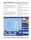
Remote Capacity
The remote capacity input allows a system controller
such as the PLC to control the capacity position during
direct I/O control.
Control Input:
• This drop-down box is not used at this time.
Scale:
• Defi nes the minimum and maximum Capacity posi-
tion between 0% & 100% for the 4-20ma input.
Offset:
• Used to correct any error in the capacity position. By
entering a value into the Adjustment entry box, that
value will be added to the total offset displayed in the
“total offset” entry box.
Section 13 • Instruments Calibration