


3 – 6
Vission 20/20 • Operation and Service Manual •Vilter/Emerson • 35391SC 1.8.5153
Volume Position:
• Reads the 0-5 volt signal back from the slide volume
motor actuator to indicate current volume position.
Suction Temperature:
• Default signal is RTD. Suction temperature calibra-
tion is set in the calibration screen.
Discharge Temperature:
• Default signal is RTD. Discharge temperature calibra-
tion is set in the calibration screen.
Oil Separator Temperature:
• Default signal is RTD. Oil separator temperature cali-
bration is set in the calibration screen.
Oil Manifold Temperature:
• Default signal is RTD. Oil manifold temperature cali-
bration is set in the calibration screen.
Process Temperature:
• Default signal is 4-20mA. Process temperature cali-
bration and range are set in the calibration screen.
Chiller Inlet Temperature:
• Default signal is 4-20mA. Measures separator level.
Chiller Inlet Temperature calibration and range are
set in the calibration screen.
Condenser Pressure:
• Default signal is 4-20mA. Condenser pressure trans-
ducer range and calibration is set in the calibration
screen.
Remote Caphold:
• Default signal is 4-20mA. Active in “Direct I/O” mode.
Adjusts the capacity of the compressor from 0-100%,
proportional to the 4-20mA signal.
Auxiliary #1 - #16:
• Flexible analog inputs that can be confi gured to con-
trol, alarm or trip.
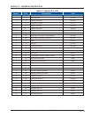
Analog Outputs:
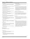
Refer to Table 2-3. Analog Outputs.
Compressor VFD:
• 4-20mA output to control compressor motor speed
with a Variable Frequency Drive (VFD).
Condenser VFD:
• 4-20mA output to control one condenser fan which is
interleaved between the remaining condenser steps
for smoother control.
% Slide Valve Position:
• 4-20mA signal that transmits the slide valve position
for remote monitoring.
Motorized Valve (V+):
• For a cool compression compressor, this 4-20mA
signal controls a motorized valve to regulate the liq-
uid refrigerant level in the oil separator. For a liquid
injection application on a standard single screw, this
4-20mA signal controls a motorized valve to regulate
the liquid refrigerant injected into the compressor for
oil cooling purposes.
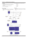
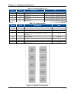
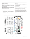
Digital & Analog I/O Boards Layout
It is important to install the boards in the proper layout.
For the correct digital and analog input/output (I/O)
board layout, see Figure 3-2. Digital I/O Board Layout.
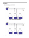
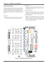
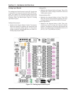
Dipswitches
• Each board has a dipswitch which sets its communi-
cations address so that it can communicate with the
CPU board. The dipswitch settings must be correct
or the I/O will not function.
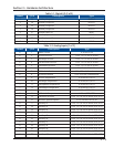
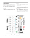
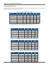
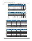
Jumpers
• Jumpers are required on the analog boards to con-
fi gure them for the type of sensors used. The jumper
table for the analog board shows the optional jump-
er confi gurations for sensors other than the default
Vilter standard. If a different sensor is to be used, the
jumpers on the analog board need to be changed. In
addition, the confi guration for this sensor must be
changed in the Instrument Calibration screen. The
following illustrations show the Vilter default con-
fi gurations for the Vission 20/20.
Section 3 • Hardware Architecture