


3 – 9
Vission 20/20 • Operation and Service Manual •Vilter/Emerson • 35391SC 1.8.5153
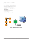
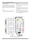
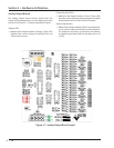
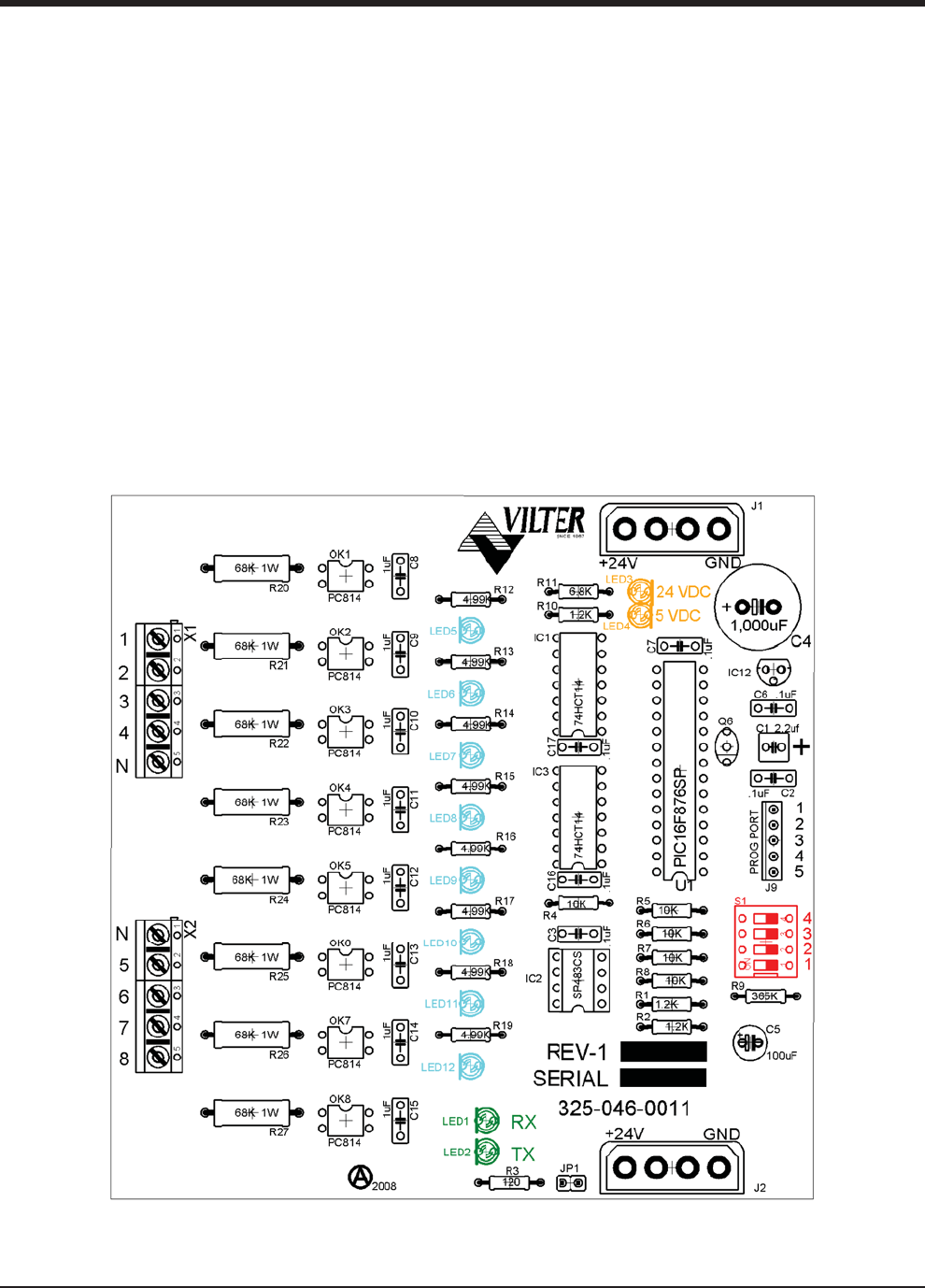
Digital Input Boards
The digital input board convert 120Vdc signals from ex-
ternal devices to signal for the Vission 20/20 program.
All the signals are digital in that the only two states avail-
able or either on or off. See board layout, Figure 3-4.
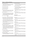
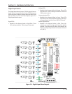
Digital Input Board Layout.
Signal LEDs:
• Marked in the diagram below in light Blue. These
LEDs indicated when a 120Vac input is detected.
Voltage LEDs:
• Marked in the diagram below in Orange. These LEDs
indicated the correct voltage of both the 5Vdc and
24Vdc power sources.
Communication LEDs:
• Marked in the diagram below in Green. These LEDs
Show the active communications between the digi-
tal output board and the Vission 20/20 CPU board.
Address Dipswitches:
• Marked in the diagram below in Red. These dip-
switches are used to assign each board its address
position. The addresses are binary and therefor the
address of a digital input board can only be addressed
as 3 (0011).
Figure 3-4. Digital Input Board Layout
Section 3 • Hardware Architecture