


3 – 11
Vission 20/20 • Operation and Service Manual •Vilter/Emerson • 35391SC 1.8.5153
Section 3 • Hardware Architecture
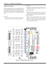
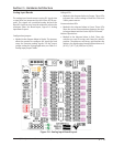
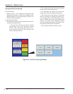
Analog Input Boards
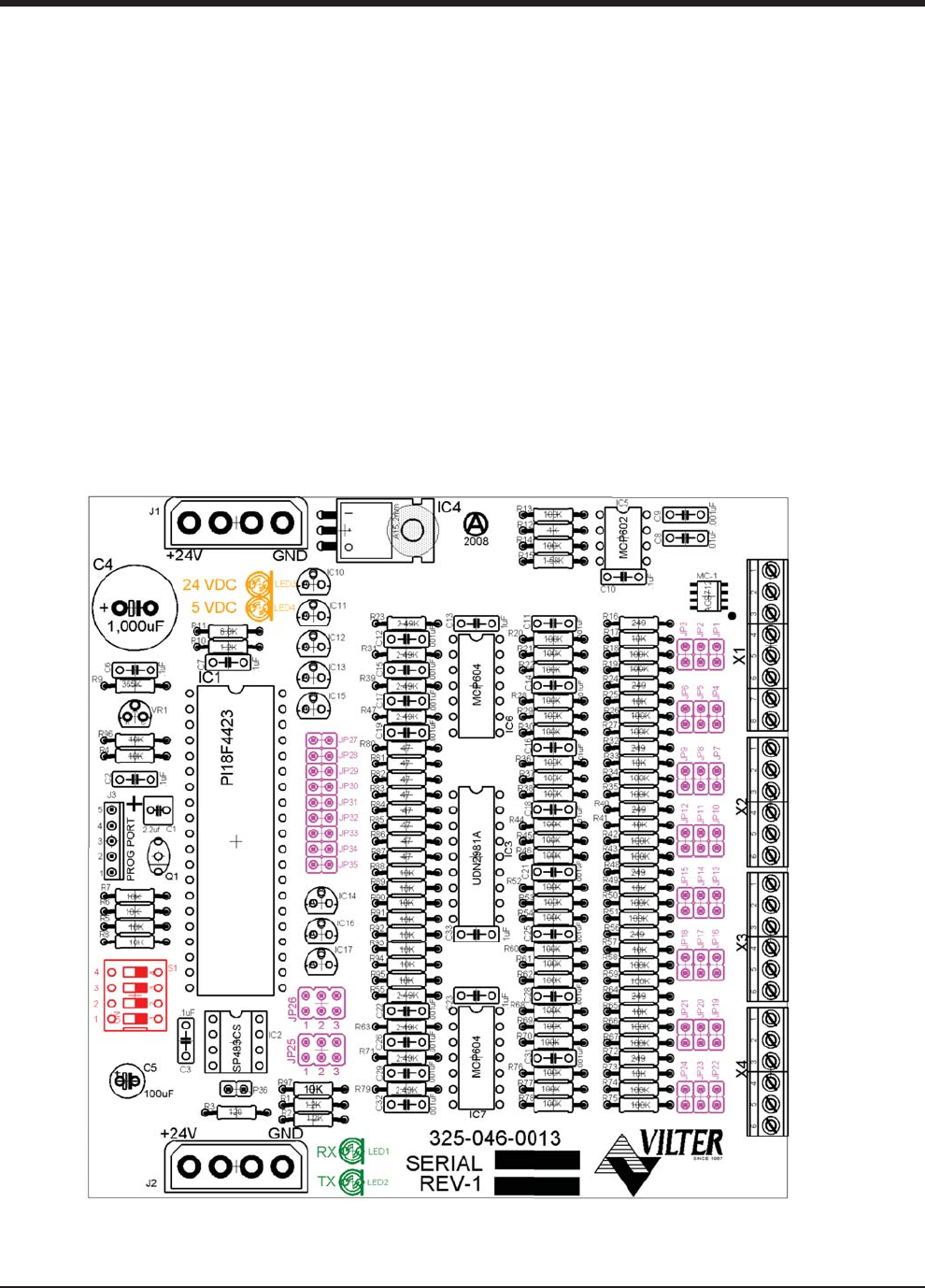
The analog input board convert varying DC signals into
a signal that can interpreted by the Vission 20/20 pro-
gram. The signals are considered analog because the
input DC signal can vary from the minimum value to the
maximum value. See board layout, Figure 3-6. Analog
Input Board Layout.
Confi guration Jumpers:
• Marked in the diagram below in Purple. The jumpers
allow the operator to confi gure the signal type and
range for incoming analog signals. For the correct
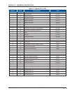
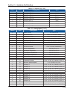
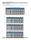
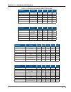
jumper setting for a giving application, see Table 2-4.
Analog Input Jumper Tables.
Voltage LEDs:
• Marked in the diagram below in Orange. These LEDs
indicated the correct voltage of both the 5Vdc and
24Vdc power sources.
Communication LEDs:
• Marked in the diagram below in Green. These LEDs
Show the active communications between the digi-
tal output board and the Vission 20/20 CPU board.
Address Dipswitches:
• Marked in the diagram below in Red. These dip-
switches are used to assign each board its address
position. The addresses are binary and therefore the
address of a digital output board will be address as 6
(0110), 7 (0111), 8 (1000) or 9 (1001).
Figure 3-6. Analog Input Board Layout