


25 – 4
Vission 20/20 • Operation and Service Manual •Vilter/Emerson • 35391SC 1.8.5153
Section 25 • Cool Compression Control
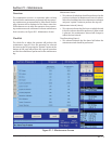
operational differences that are mostly associated with
the compressor safeties:
1. The Cool Compression program ignores,
• Low Oil Separator Alarm / Trip at start
• High Filter Differential at start
• Prelube Oil Pressure Alarm and Trip
• Run Oil Pressure Alarm and Trip (Pressure
Ratios are monitored instead).
• High Discharge Temp Alarm and Trip
(Discharge Temp Superheat is monitored)
• Low Suction Temp Alarm and Trip
• Low Oil Injection Temp Alarm and Trip
• High Oil Injection Temp Alarm and Trip
2. SOI solenoid is forced on for fi rst 60 seconds of run-
ning and 10 minutes after compressor is stopped.
3. Auto Load Enabled: When Auto Load is engaged at
start, it then maintains the position of capacity slide to
the Auto Load limit (approx : 30 %, but less than 50 %).
It displays status message “Cool Compression Capacity
Hold” when it is running. Unless Auto load is disengaged
compressor will run at auto load limit position. Auto load
disengages if enough Pressure Ratio is built (typically
more than 2.04) or setpoints are achieved.
4. SOI Solenoid: During normal operation if pressure ra-
tio drops to a lower value (typically below 2.00) then it
energizes SOI solenoid and maintains the position of ca-
pacity slide to the SOI Load limit (approx : 30 %, less than
50 %). It also displays status message “Cool Compression
Capacity Hold”. If enough Pressure Ratio is built across
the compressor (typically more than 2.04), it again re-
sumes the run mode and control normally.
5. It performs Cool Compression specifi c checks periodi-
cally like:
• Controlling the liquid level positioning valve
as liquid ammonia level changes .
• Low / high Pressure Oil Injection ports control
as Pressure Ratio and Superheat temperature
changes.
Supplemental Oil Cooling Solenoids
• Some cool compression units will have supplemental
oil cooling solenoids. One is called the suction liquid
injection solenoid and is controlled via discharge su-
perheat. When the discharge superheat reaches 5°F,
the solenoid is turned on. When it falls back to below
4°F, the solenoid is turned off. An additional solenoid
(referenced as SV4 – as called the High Press Ratio
solenoid) provides supplemental oil cooling based on
pressure ratio. When the pressure ratio rises above
5.0, the solenoid is turned on. When the pressure ra-
tio falls back to below 4.8, the solenoid is turned off.
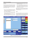
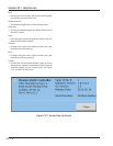
Level Switches
• There are two level switches in the oil separator, a
“high” and a “low”. During normal running opera-
tion, the oil level is above both switches. When the oil
level starts to drop and opens the high level switch,
a 10 minute timer starts. When the timer elapses a
fl ashing “add oil to middle of sight glass” message ap-
pears on the main screen. When the operator adds
enough oil to close the high level switch, the mes-
sage disappears.
NOTICE
If oil is not added and the oil level continues to drop
thereby opening the “low” oil level switch, a 10 minute
timer starts again. When the timer elapses, the com-
pressor shutdowns immediately and displays “Low Oil
Level” failure. If enough oil is added to close the low
level switch, then this will allow the opeator to press the
reset button and clear the “Low Oil Level” failure and
“Add Oil” message.
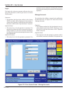
Oil Level Messaging After Compressor Stops
• The low level switch is monitored after the compres-
sor stops. If the switch opens after the compressor
stops, a two minute timer starts. If the switch stays
open, and the timer expires, a failure is generated
called “Lo Oil Level Fail after Stop” and the compres-
sor is disabled from restarting until oil is added to
close the low level switch. Note that this failure is
generated ONLY when the low level switch opens af-
ter the compressor stops.