


12 – 2
Vission 20/20 • Operation and Service Manual •Vilter/Emerson • 35391SC 1.8.5153
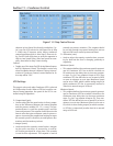
of the volume actuator. The output is connected to
terminal 15 and is the 5th LED down on card 1.
Volume Decrease Motor:
• Activates the output assigned to the decrease input
of the volume actuator. The output is connected to
terminal 16 and is the 6th LED down on card 1.
Oil Separator Heater
• Activates the output assigned to the oil separator
heater. The output is connected to terminal 17 and is
the 7th LED down on card 1.
Trip:
• Deactivates the output during a trip or inhibit con-
dition. This is a reverse acting output. The output is
connected to terminal 18 and is the bottom LED on
card 1.
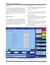
Slide Valve Setpoint # 1 (Economizer):
• Activates the output typically assigned to the econo-
mizer solenoid, but can be changed by the operator.
The output is connected to terminal 21 and is the 1st
LED on card 2.
Slide Valve Setpoint # 2 (Hot Gas Bypass):
• Activates the output typically assigned to the hot gas
bypass solenoid, but can be changed by the operator.
The output is connected to terminal 22 and is the 2nd
LED on card 2.
Alarm:
• Activates the output during an alarm condition. This
is a reverse acting output. The output is connected to
terminal 23 and is the 3rd LED on card 2.
Liquid Injection # 1:
• Activates the output assigned to the liquid injection
solenoid. The output is connected on terminal 25
and is the 5th LED on card 2.
Liquid Injection # 2:
• Not currently enabled
Remote Enabled:
• Activates the output assigned to notify a central con-
trol system of the Vission 20/20 run status. The out-
put is connected to terminal 27 and is the 7th LED on
card 2.
Shunt Trip:
• Activates the output during a false start condition
and the emergency stop timer has expired. This out-
put could be wired the a breaker with a shunt trip that
feeds power to a starter to force a shutdown. The
output is connected to terminal 28 and is the 8th LED
on card 2.
Condenser Step # 1:
• Activates the output assigned to the 1st step of the
condenser. The output is connected to terminal 41
and is the 1st LED on card 4.
Condenser Step # 2:
• Activates the output assigned to the 2nd step of the
condenser. The output is connected to terminal 42
and is the 2nd LED on card 4.
Condenser Step # 3:
• Activates the output assigned to the 3rd step of the
condenser. The output is connected to terminal 43
and is the 3rd LED on card 4.
Condenser Step # 4:
• Activates the output assigned to the 4th step of the
condenser. The output is connected to terminal 44
and is the 4th LED on card 4.
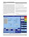
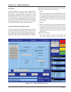
Analog Outputs
The Analog Output (AO) selections allow the operator to
enter a desired value of the output then turn on the out-
put. The operator will have to measure the output using
meter capable of measuring a 4-20mA signal.
Compressor VFD:
• Sets the analog output assigned to the compressor
VFD. The output is connected to AO #1 on card 10.
Condenser VFD:
• Sets the analog output assigned to the condenser
VFD. The output is connected to AO #2 on card 10.
% Slide Valve Position
• Sets the analog output assigned to the Slide Value
position used to inform a central control system of
the capacity position. The output is connected to AO
#3 on card 10.
Liquid injection Motorized Valve:
• Sets the analog output assigned to the liquid injec-
tion motorized value position. The output is connect-
ed to AO #4 on card 10.
Section 12 • Service Options