


18 – 3
Vission 20/20 • Operation and Service Manual •Vilter/Emerson • 35391SC 1.8.5153
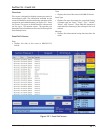
• High Alarm:
• This defi nes the upper limit of the input value,
that when exceeded will generate an alarm.
• Low Trip:
• Defi nes the lower limit of the input value that
when exceeded will generate a trip.
• High Trip:
• Defi nes the upper limit of the input value that
when exceeded will generate a trip.
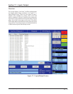
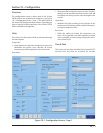
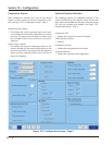
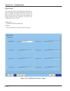
Analog Outputs
This screen allows to map any standard analog input or
auxiliary input to any of the four analog auxiliary out-
puts. There are two pages of auxiliary output confi gura-
tion, each consists of two analog auxiliary outputs.
• Active Input:
• Active Input can be selected from avail-
able standard analog inputs or auxiliary inputs.
Selected Active Input gets mapped to auxiliary
output.
• Run Always:
• “Run Always” option can be selected to en-
able mapped auxiliary output irrespective of the
compressor’s run state. If “Run Always” is not
selected then the mapped auxiliary output is
enabled only when compressor is running.
• Trigger:
• Trigger confi guration is used to enable / dis-
able auxiliary output according to the confi g-
ured trigger input. Trigger input can be selected
from available standard analog inputs , auxiliary
analog inputs or digital inputs. Trigger value
and differential in combination with trigger
type (“enable if above / On” or “enable if below /
Off”) enables or disables auxiliary output.
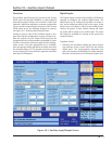
Control
Auxiliary outputs can be PID Controlled or Scalable
Controlled.
P = Proportional (gain):
• Used to adjust the auxiliary output in direct propor-
tion to the difference between the control setpoint
and the active input . The proportional term is a unit
less quantity and is used for coarse adjustment. This
setpoint should be set to the lowest value that gives
adequate control system response. Increasing the
proportional setting increases the control system’s
sensitivity to small process fl uctuations and the ten-
dency to hunt.
I = Integral (reset):
• Used to integrate the error over time, to account for
a small error that has persisted for a long time. This
quantity is used for fi ne adjustment. This setpoint is
used to smooth out process variations. This setpoint
should be set high enough to prevent hunting but
not too high or it will cause control system overshoot.
D = Derivative (rate):
• Used to account for how fast the error is changing,
positively or negatively.
Scalable Control:
• Minimum Input / Maximum Input:
• These setpoints defi nes minimum and maxi-
mum Input range for confi gured active input .
• Minimum Output / Maximum Output:
• These setpoints defi nes minimum and maxi-
mum output. The Auxiliary output produces a
linear value based on these settings.
Section 18 • Auxiliary Input / Output