


3 – 8
Vission 20/20 • Operation and Service Manual •Vilter/Emerson • 35391SC 1.8.5153
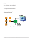
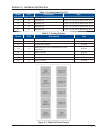
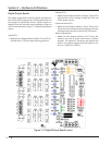
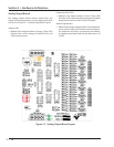
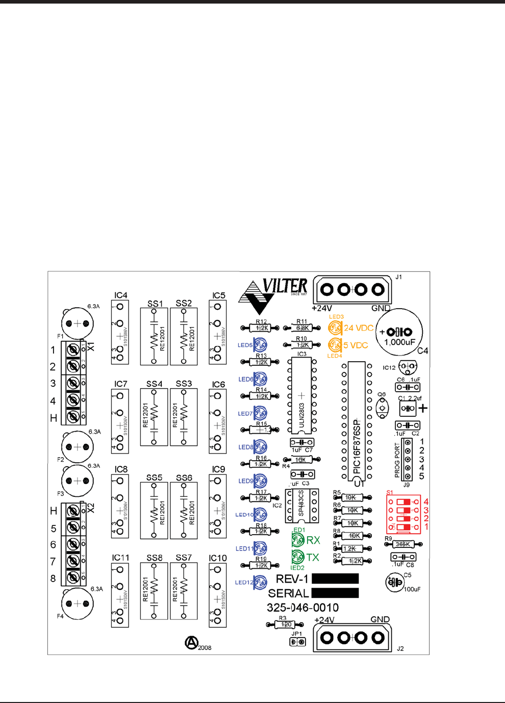
Digital Output Boards
The digital output board convert signals generated by
the Vission 20/20 program into 120Vac signals that can
be energize or signal other devices. All the signals are
digital in that the only two states available or either on
or off. See board layout, Figure 3-3. Digital Output Board
Layout.
Signal LED’s:
• Marked in the diagram below in Blue. These LED’s in-
dicated when a 120Vac output is being produced.
Voltage LED’s:
• Marked in the diagram below in Orange. These LED’s
indicated the correct voltage of both the 5Vdc and
24Vdc power sources.
Communication LED’s:
• Marked in the diagram below in Green. These LED’s
Show the active communications between the digi-
tal output board and the Vission 20/20 CPU board.
Address Dipswitches:
• Marked in the diagram below in Red. These dip-
switches are used to assign each board its address
position. The addresses are binary and therefor the
address of a digital output board will either be ad-
dress as 1 (0001) or 2 (0010).
Figure 3-3. Digital Output Board Layout
Section 3 • Hardware Architecture