


3 – 3
Vission 20/20 • Operation and Service Manual •Vilter/Emerson • 35391SC 1.8.5153
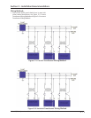
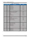
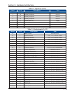
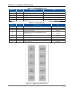
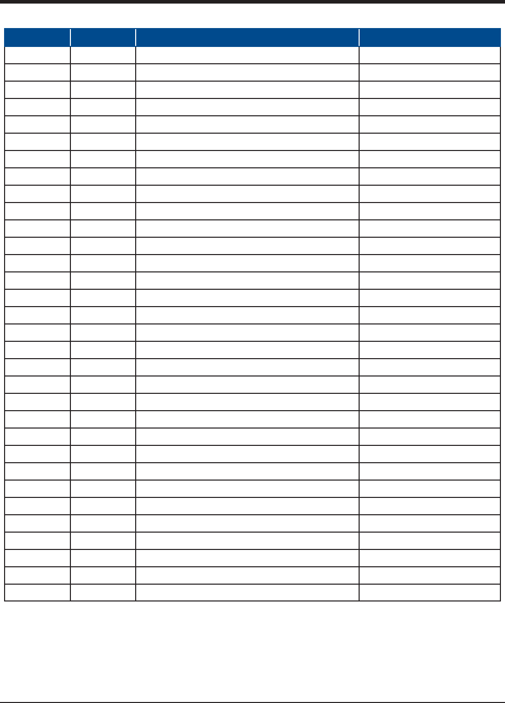
Table 3-1. Digital I/O (1 of 2)
Board I/O # Description Type
1 1 Compressor Start OUTPUT
1 2 Oil Pump Start OUTPUT
1 3 Capacity Increase OUTPUT
1 4 Capacity Decrease OUTPUT
1 5 Volume Increase OUTPUT
1 6 Volume Decrease OUTPUT
1 7 Oil Separator Heater OUTPUT
2 8 Trip indicator (ON=Normal) OUTPUT
2 9 Slide Valve Set point #1 (Economizer) OUTPUT
2 10 Slide Valve Set point #2 (Hot Gas) OUTPUT
2 11 Alarm OUTPUT
212Unused OUTPUT
2 13 Liquid Injection #1 OUTPUT
2 14 Liquid Injection #2 OUTPUT
2 15 Remote Enabled OUTPUT
2 16 Shunt Trip OUTPUT
3 17 Comp Motor Starter Auxiliary Contact INPUT
3 18 High Level Shutdown INPUT
3 19 Oil Level Float Switch #1 INPUT
3 20 Oil Level Float Switch #2 INPUT
3 21 Remote Setpoint #1/#2 Selection INPUT
3 22 Remote Start/Stop INPUT
3 23 Remote Capacity Increase INPUT
3 24 Remote Capacity Decrease INPUT
4 25 Condenser Step #1 OUTPUT
4 26 Condenser Step #2 OUTPUT
4 27 Condenser Step #3 OUTPUT
4 28 Condenser Step #4 OUTPUT
4 29 Auxiliary Input #1 INPUT
4 30 Auxiliary Input #2 INPUT
4 31 Auxiliary Input #3 INPUT
4 32 Auxiliary Input #4 INPUT
Section 3 • Hardware Architecture