


7 – 3
Vission 20/20 • Operation and Service Manual •Vilter/Emerson • 35391SC 1.8.5153
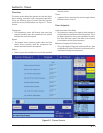
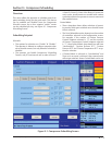
Compressor Inhibits
The Vission 20/20 uses several start inhibits to prevent
the compressor from starting to protect the compres-
sor and the refrigeration system. While starting the
compressor, the inhibits are checked fi rst before the oil
pump is started or the motor is started. The failed starts
due to an inhibit does not count toward any of the anti-
recycle timers including hot starts. The Inhibits uses the
alarm setpoint to trigger an aborted start and message.
All inhibits will be logged in the event list.
Safety Failure Messages
Low Suction Pressure Trip
• This message will appear when the suction pressure
falls below the safety setting of the Low Suction Pres-
sure Trip Setpoint No.1 or No. 2.
High Discharge Pressure Trip
• This message will appear when the discharge pres-
sure exceeds the safety setting of the Hi Dsch Press
Trip Setpoint No. 1 or No. 2.
Low Suction Temp Trip
• This message will appear when the suction tempera-
ture falls below the safety setting of the Low Suction
Temperature Trip setpoint.
High Discharge Temp Trip
• This message will appear when the discharge tem-
perature rises above the safety setting of the High
Discharge Temperature Trip setpoint.
Low Oil Separator Temp Trip
• This message will appear when the Oil Separator
Temp is below the Low Oil Separator Start Temp Trip
setpoint. In addition this message will appear after
the Oil Separator Temp Safety Changeover timer
times out and the Oil Separator temperature fails to
rise above the Low Oil Separator Start Temp Reset af-
ter the compressor is started.
Low Oil Separator Temp Trip
• This message will appear when the Oil Separator
Temp is below the Low Oil Separator Run Temp
Reset setpoint after the Oil Separator Temp Safety
Changeover timer times out.
Low Process Temp Trip
• This message will appear when the Process Control
Temperature falls below the safety setting of the Lo
Control Temperature Trip Setpoint.
Prelube Oil Pump Inhibit
• This message will appear when the Prelube Oil
Pressure (Manifold minus Discharge) has remained
below the Prelube Oil Pressure Reset setpoint. The
oil pump will try to generate “prelube pressure” for
the time period of the Low Oil Pressure Safety Bypass
timer setting.
Low Oil Pressure Trip
• This message will appear when the Running Oil
Pressure (Manifold minus Suction) has remained be-
low the low Oil Pressure Reset setpoint when the Oil
Pressure Bypass Start timer times out. This message
will also appear when the Running Oil Pressure falls
below the Low Oil Pressure trip setpoint after the Low
Oil Pressure Safety Bypass timer times out.
Low Oil Injection Temp Trip
• This message will appear when the Oil Injection tem-
perature falls below the Low Oil Injection Temperature
trip setpoint. This message will also appear when the
Oil Injection temperature fails to rise above the Low
Oil Injection Temperature reset setpoint after the
Low Oil Injection Temp Bypass timer times out.
High Oil Injection Temp Trip
• This message will appear when the Oil Injection
temperature rises above the High Oil Injection
Temperature trip setpoint.
High Filter Differential Trip
• This message will appear if the Filter Differential
Pressure rises above the High Fltr Diff Press – Start
setpoint before the Filter Differential Pressure Safety
Changeover timer times out.
High Filter Differential Trip
• This message will appear if the Filter Differential
pressure rises above the High Fltr Diff Press Run
setpoint after the Filter Differential Pressure Safety
Changeover timer times out.
High Motor Current Trip
• This message will appear if the motor amperage rises
above the Hi Motor Amps trip setpoint.
Compressor Interlock Trip
• This message will appear if the Motor Auxiliary con-
tact fails to close before the Compressor Starter
Auxiliary Contact Bypass timer times out. Refer to
wiring diagram.
High Level Shutdown Trip
• This message will appear when power is removed
from the input module that is designated as “Auxiliary
#1 Safety” (please refer to your wiring diagram).
Section 7 • Alarms and Trips