


Vission 20/20 • Operation and Service Manual •Vilter/Emerson • 35391SC 1.8.5153
TOC - 2
Section 4 • Main Screen
Overview ..........................................................................................................................................4-1
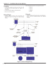
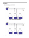
Figure 4-1. Digital I/O Board Layout...................................................................................................4-1
Top Status Bar ...................................................................................................................................4-2
Figure 4-2. Top Status Bar .................................................................................................................4-2
Parameter Bar ...................................................................................................................................4-3
Figure 4-3. Parameter Bar .................................................................................................................4-3
Figure 4-4. Unit Start Pop-Up Window ..............................................................................................4-4
Bottom Status Bar .............................................................................................................................4-5
Figure 4-5. Bottom Status Bar ...........................................................................................................4-5
Splash Screen ....................................................................................................................................4-6
Figure 4-6. Splash Screen ..................................................................................................................4-6
Section 5 • Menu Screen
Overview ..........................................................................................................................................5-1
Navigation Buttons ...........................................................................................................................5-1
Figure 5-1. Menu Screen ...................................................................................................................5-2
Section 6 • Compressor Control
Overview ..........................................................................................................................................6-1
Pulse Proportional Control ................................................................................................................6-1
Figure 6-1. Compressor Control Screen .............................................................................................6-1
Auto-Cycle ........................................................................................................................................6-2
Figure 6-2. Proportional Band & Setpoint ..........................................................................................6-2
Variable Frequency Drive (VFD) .........................................................................................................6-3
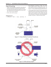
Figure 6-3. VFD One-Step Control Method ........................................................................................6-3
Figure 6-4. VFD Two-Step Control Method ........................................................................................6-3
Pumpdown Control...........................................................................................................................6-4
Pulldown Control ..............................................................................................................................6-5
Control Mode....................................................................................................................................6-6
Stop load & Force unload ..................................................................................................................6-6
Capacity Slide Triggered Outputs ......................................................................................................6-6
Volume Slide Position Offset .............................................................................................................6-6
Soft Load ..........................................................................................................................................6-6
Load Anticipating ..............................................................................................................................6-7
Oil Control ........................................................................................................................................6-7
Liquid Injection .................................................................................................................................6-7
Section 7 • Alarms and Trips
Overview ..........................................................................................................................................7-1
Alarms and Trips Setpoints ................................................................................................................7-1
Figure 7-1. Alarms and Trips Screen ...................................................................................................7-1
Compressor Inhibits ..........................................................................................................................7-3
Safety Failure Messages ....................................................................................................................7-3
Section 8 • Timers
Overview ..........................................................................................................................................8-1
Timer Setpoints ................................................................................................................................8-1
Figure 8-1. Timers Screen ..................................................................................................................8-1
Section 9 • Compressor Scheduling
Overview ..........................................................................................................................................9-1
Scheduling Setpoint ..........................................................................................................................9-1
Figure 9-1. Compressor Scheduling Screen .......................................................................................9-1
Section Title Section Number
Table of Contents