


14 – 8
Vission 20/20 • Operation and Service Manual •Vilter/Emerson • 35391SC 1.8.5153
Section 14 • Slide Calibration
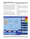
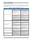
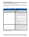
Table 14-3. LED Blink Codes and Troubleshooting Guide (2 of 2)
Flash Pattern
* = ON - = OFF
Meaning
*--*--*-----------------
The motor is overheated. The actuator motor will not
run until it cools. Once the motor cools, the actuator will
resume normal operation.
Motor overheating is sometimes a problem in hot
humid environments when process conditions demand
that the slide valve actuators reposition often. Solutions
are available; consult your Vilter authorized distributor
for details.
Another possible cause for this error is a stuck motor
thermal switch. The thermal switch can be tested by
measuring the DC voltage with a digital multimeter be-
tween the two TS1 wire pads (see Note 2). If the switch
is closed (normal operation) you will measure 0 Volts.
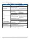
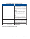
*********************
The 24V supply voltage is low. This will occur momen-
tarily when the actuator is powered up and on power
down.
If the problem persists, measure the voltage using a
digital multimeter between terminals 3 and 4 of the
small terminal block. If the voltage is less than 24V, the
problem is in the supply to the board.
If the voltage is >= 24V, replace the actuator..
-********************
The EEPROM data is bad. This is usually caused by loss of
24V power before the calibration procedure was com-
pleted. The actuator will not move while this error code
is being displayed. To clear the error, calibrate the actua-
tor. If this error has occurred and the cause was not loss
of 24V power during calibration, the EEPROM memory
is bad and the actuator will need to be replaced.
*****----*--------------
Microcontroller program failure. Please notify your
Vilter authorized distributor.
Note 2: The TS1 wire pads are where the motor thermal switch leads solder into the circuit board. They are clearly
marked on the board silkscreen legend and are oriented at a 45° angle.