


Vission 20/20 • Operation and Service Manual •Vilter/Emerson • 35391SC 1.8.5153
TOC - 6
Table 3-1. Digital I/O .........................................................................................................................3-3
Table 3-2. Analog Inputs....................................................................................................................3-5
Table 3-3. Analog Outputs.................................................................................................................3-7
Table 3-4. Analog Input Jumper Tables ..............................................................................................3-12
Table 14-1. Command Shaft Rotation Required By Actuator ..............................................................14-4
Table 14-2. Slide Valve Troubleshooting Guide ..................................................................................14-5
Table 14-3. LED Blink Codes and Troubleshooting Guide ....................................................................14-7
Table 22-1. Security Access Levels .....................................................................................................22-3
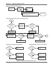
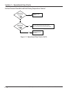
Figure 1-1. Operational Flow Charts ..................................................................................................1-1
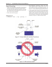
Figure 2-1. Vission 20/20 with Individual Transformer .......................................................................2-1
Figure 2-2. EMI and Vission 20/20 .....................................................................................................2-1
Figure 2-3. Ground Wiring ................................................................................................................2-2
Figure 2-4. Mixed Voltage Wiring ......................................................................................................2-2
Figure 2-5. Correct Transformer Wiring Method ...............................................................................2-3
Figure 2-6. Incorrect Transformer Wiring Method .............................................................................2-3
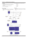
Figure 3-1. Hardware Architecture Overview ....................................................................................3-1
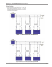
Figure 3-2. Digital I/O Board Layout...................................................................................................3-7
Figure 3-3. Digital Output Board Layout ............................................................................................3-8
Figure 3-4. Digital Input Board Layout ...............................................................................................3-9
Figure 3-5. Digital Input-Output Board Layout ...................................................................................3-10
Figure 3-6. Analog Input Board Layout ..............................................................................................3-11
Figure 3-7. Analog Output Board Layout ...........................................................................................3-14
Figure 4-1. Digital I/O Board Layout...................................................................................................4-1
Figure 4-2. Top Status Bar .................................................................................................................4-2
Figure 4-3. Parameter Bar .................................................................................................................4-3
Figure 4-4. Unit Start Pop-Up Window ..............................................................................................4-4
Figure 4-5. Bottom Status Bar ...........................................................................................................4-5
Figure 4-6. Splash Screen ..................................................................................................................4-6
Figure 5-1. Menu Screen ...................................................................................................................5-2
Figure 6-1. Compressor Control Screen .............................................................................................6-1
Figure 6-2. Proportional Band & Setpoint ..........................................................................................6-2
Figure 6-3. VFD One-Step Control Method ........................................................................................6-3
Figure 6-4. VFD Two-Step Control Method ........................................................................................6-3
Figure 7-1. Alarms and Trips Screen ...................................................................................................7-1
Figure 8-1. Timers Screen ..................................................................................................................8-1
Figure 9-1. Compressor Scheduling Screen .......................................................................................9-1
Figure 10-1. Compressor Sequencing Screen ....................................................................................10-1
Figure 11-1. Condenser Control Screen .............................................................................................11-1
Figure 11-2. Step Control Screen .......................................................................................................11-3
Figure 12-1. Service Options Screen ..................................................................................................12-1
Figure 13-1. Instruments Calibration Screen .....................................................................................13-1
Figure 14-1. Slide Calibration Screen .................................................................................................14-1
Figure 14-2. Photochopper ...............................................................................................................14-3
Figure 15-1. Trend Chart Screen ........................................................................................................15-1
Figure 15-2. Trend Setup Screen ........................................................................................................15-3
Figure 16-1. Event List Screen ............................................................................................................16-1
Figure 17-1. Input/Output Screen .....................................................................................................17-1
Figure 18-1. Auxiliary Input/Output Screen .......................................................................................18-1
Figure 19-1. Configuration Screen - Page 1 ........................................................................................19-1
Figure 19-2. Configuration Screen - Page 2 ........................................................................................19-4
Figure 19-3. Configuration Screen - Page 3 ........................................................................................19-6
List of Tables and Figures
Table/Figure Page Number