Vission 20/20 • Operation and Service Manual •Vilter/Emerson • 35391SC 1.8.5153
TOC - 4
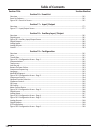
Section 16 • Event List
Overview ..........................................................................................................................................16-1
Event list Columns .............................................................................................................................16-1
Figure 16-1. Event List Screen ............................................................................................................16-1
Section 17 • Input / Output
Overview ..........................................................................................................................................17-1
Figure 17-1. Input/Output Screen .....................................................................................................17-1
Section 18 • Auxiliary Input / Output
Overview ..........................................................................................................................................18-1
Digital Inputs ....................................................................................................................................18-1
Figure 18-1. Auxiliary Input/Output Screen .......................................................................................18-1
Digital Outputs .................................................................................................................................18-2
Analog Inputs ...................................................................................................................................18-2
Analog Outputs ................................................................................................................................18-3
Control .............................................................................................................................................18-3
Section 19 • Configuration
Overview ..........................................................................................................................................19-1
Units .................................................................................................................................................19-1
Time & Date ......................................................................................................................................19-1
Figure 19-1. Configuration Screen - Page 1 ........................................................................................19-1
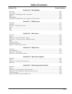
Communications ..............................................................................................................................19-2
Touchscreen .....................................................................................................................................19-2
Anti-Recycle......................................................................................................................................19-2
Restart On Power Failure ...................................................................................................................19-3
Compressor Sequencing ...................................................................................................................19-3
Language ..........................................................................................................................................19-3
Model & Refrigerant ..........................................................................................................................19-3
Figure 19-2. Configuration Screen - Page 2 ........................................................................................19-4
Compressor Control ..........................................................................................................................19-4
Optional Function Selection ..............................................................................................................19-4
Condenser Control ............................................................................................................................19-5
Oil Pump ...........................................................................................................................................19-5
Oil Cooling ........................................................................................................................................19-5
Motor Current Device .......................................................................................................................19-5
Figure 19-3. Configuration Screen - Page 3 ........................................................................................19-6
Digital Inputs ....................................................................................................................................19-6
Analog Inputs ...................................................................................................................................19-7
Figure 19-4. Configuration Screen - Page 4 ........................................................................................19-7
Figure 19-5. Configuration Screen - Page 5 ........................................................................................19-8
Analog Outputs ................................................................................................................................19-8
Digital Outputs .................................................................................................................................19-8
I/O Configuration ..............................................................................................................................19-9
Figure 19-6. Configuration Screen - Page 6 ........................................................................................19-9
Section Title Section Number
Table of Contents


