


18 – 2
Vission 20/20 • Operation and Service Manual •Vilter/Emerson • 35391SC 1.8.5153
Inhibit Check:
• Selecting this checkbox enables the inhibit function
of the Vission 20/20 for the desired digital input. An
inhibit check prevents the compressor from starting
if the condition is true where a trip will shut down
the compressor after it as started. The inhibit can be
selected to inhibit on a high or low input and can be
selected to work with or without the alarm and trip
function
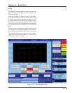
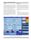
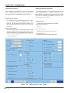
Digital Outputs
The digital outputs section of the Auxiliary I/O screen al-
lows an operator to confi gure the auxiliary digital out-
puts. The digital output can be confi gured to activate
(go High, 120vac) based on either a digital input or a
specifi ed level on an analog input. Every digital and ana-
log input in the Vission 20/20 are made available for con-
trolling a digital output.
Analog Input:
• Selecting the Analog Input radio button fi lls the
Active Input drop-down box with all available analog
inputs. One of the analog inputs can then be selected
to control the digital outputs.
Digital Input:
• Selecting the Digital Input radio button fi lls the
Active Input drop-down box with all available digital
inputs. One of the digital inputs can then be selected
to control the digital outputs.
Run Always:
• Selecting this checkbox enables the function that
controls the digital output to operate only when the
compressor is running or runs all the time.
Analog Trigger:
• The analog trigger toggles the digital output based
on a specifi ed value plus the specifi ed differential
value.
• Analog Trigger value:
• This defi nes the specifi ed value in which the
output will toggle. This is an absolute value
and not based on units. For example, 100 could
mean temperature or pressure depending on
the type of input selected.
• N/O & N/C:
• Choosing the Normally Open (N/O) or
Normally Closed (N/C) radio buttons defi nes
what the output will be above or below the trig-
ger value. In the N/O setting, the output will be
off (0vac) while the input value is below the trig-
ger value.
• Differential:
• This is the differential around the trigger val-
ue. For example, if a trigger value of 100 is en-
tered with a differential of 1, then as the value
increases to 101, the output will be triggered. If
the value decreases to 99, then the output will
be toggled in the opposite direction.
Digital Relay:
• The digital relay option is used to pass along the in-
formation from a digital input to another control de-
vice or to operate a peripheral device. This output can
be confi gured to either refl ect the selected input or
show the opposite value.
• Mirror:
• Selecting this option will produce a high out-
put when the selected input is High; and pro-
duce a low output when the selected input is
low.
• Invert:
• Selecting this option will produce a low out-
put when the selected input is high; and pro-
duce a High output when the selected input is
low.
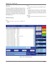
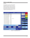
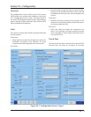
Analog Inputs
The Analog inputs section of the auxiliary I/O screen al-
lows an operator to defi ne the function of an instrument
connected to the Vission 20/20. The analog inputs can
be confi gured to simply monitor an input for informa-
tional purposes or used as a control input for the auxil-
iary digital and analog outputs. The analog inputs can
also be confi gured to alarm, trip, and inhibit on specifi ed
values.
• Alarm / Trip:
• This drop-down box allows the operator to
select whether the analog input should gener-
ate an alarm, trip, or both when the input value
exceeds the limits entered into the alarm and
trip entry boxes.
• Inhibit:
• Selecting this checkbox will prevent a start if
the input value exceeds the alarm limit values.
• Low Alarm:
• This defi nes the lower limit of the input value
that when exceeded will generate an alarm.
Section 18 • Auxiliary Input / Output