3 – 4
Vission 20/20 • Operation and Service Manual •Vilter/Emerson • 35391SC 1.8.5153
High Level Shutdown Input:
• This input must be energized in order for the com-
pressor to operate. If de-energized, the compressor
will shut down and issue a high level trip.
Oil Level Float Switch #1 Input:
• Used for Cool Compression.
Oil Level Float Switch #2 Input:
• Used for Cool Compression.
Remote Select #1/#2 Input:
• This input enables or disables remote I/O control.
Energizing this input enables the Remote Capacity
Increase and Remote Capacity Decrease inputs.
Remote Start/Stop Input:
• If the compressor is enabled for remote I/O control,
this input is enabled. Energizing this input will issue
a start for the compressor as long as it is available to
run. De-energizing this input stops the compressor.
Remote Capacity Increase Input:
NOTE
The scan interval on the remote increase and
decrease inputs is approximately ONE SECOND.
Please take that into account when developing
a control scheme using the remote increase and
remote decrease inputs for compressor control.
• If the compressor is enabled for remote I/O control,
this input is enabled. Operational only when the com-
pressor is running. Energizing this input will increase
the slide valve position.
• The slide valve will continuously increase as long as
this input is energized. The slide valve will not in-
crease when this input is de-energized.
Remote Capacity Decrease Input:
• Operational only when the compressor is running.
This input is enabled if the compressor is enabled
for remote I/O control. Energizing this input will de-
crease the slide valve position. The slide valve will
continuously decrease as long as this input is ener-
gized. The slide valve will not decrease when this in-
put is de-energized.
Condenser Step #1 Output:
• This output is enabled when condenser control op-
tion is selected. A condenser fan or pump will be
turned on or off by this output.
Condenser Step #2 Output:
• This output is enabled when condenser control op-
tion is selected. A condenser fan or pump will be
turned on or off by this output.
Condenser Step #3 Output:
• This output is enabled when condenser control op-
tion is selected. A condenser fan or pump will be
turned on or off by this output.
Condenser Step #4 Output:
• This output is enabled when condenser control op-
tion is selected. A condenser fan or pump will be
turned on or off by this output.
Auxiliary Inputs #1 - #8:
• Optional inputs that can be confi gured as an alarm
or trip. Typically connected to external switched
devices.
Auxiliary Outputs #1 - #4:
• Optional inputs that can be confi gured as an alarm
or trip. Typically connected to external switched
devices.
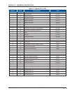
Analog Inputs
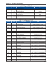
Refer to Table 2-2. Analog Inputs.
Motor Current:
• Default is a 0-5 Amp current transformer (CT). Current
transformer ratio is set in the calibration screen.
Suction Pressure:
• Default signal is 4-20mA. Suction pressure trans-
ducer range and calibration is set in the calibration
screen.
Discharge Pressure
• Default signal is 4-20mA. Discharge pressure trans-
ducer range and calibration is set in the calibration
screen.
Oil Filter Inlet Pressure:
• Default signal is 4-20mA. Oil fi lter pressure trans-
ducer range and calibration is set in the calibration
screen.
Oil Manifold Pressure:
• Default signal is 4-20mA. Oil manifold pressure trans-
ducer range and calibration is set in the calibration
screen.
Economizer Pressure:
• Default signal is 4-20mA. Economizer pressure trans-
ducer range and calibration is set in the calibration
screen.
Slide Valve Position:
• Reads the 0-5 volt signal back from the slide posi-
tion motor actuator to indicate current slide valve
position.
Section 3 • Hardware Architecture


